
Circuit analysis is one of the most fundamental and essential areas in electrical engineering. Whether you are a first-year engineering student, preparing for competitive exams, or working in power systems, electronics, or industrial automation, a strong understanding of circuit analysis is non-negotiable. It forms the backbone of system design, troubleshooting, optimization, and performance evaluation.
This complete guide covers the core principles, laws, techniques, and practical applications of circuit analysis in a structured and professional manner. By the end, you will have a clear understanding of both theoretical foundations and real-world implementation strategies.
What Is Circuit Analysis?
Circuit analysis is the systematic process of determining electrical quantities such as voltage, current, and power in an electrical network. It applies mathematical techniques and physical laws to evaluate circuit behavior under various conditions.
A circuit typically consists of:
- Voltage or current sources
- Passive components (resistors, inductors, capacitors)
- Active components (dependent sources, semiconductors)
- Interconnecting conductors
The goal of analysis is to understand how energy flows and how components interact.
Basic Electrical Quantities
Understanding circuit analysis begins with mastering four fundamental electrical quantities: voltage, current, resistance, and power. These are not just definitions — they describe how electrical energy moves, interacts, and behaves inside any electrical system.
Voltage (V)
Voltage, also called electric potential difference, is the force that pushes electric charges through a conductor. It is measured in volts (V).
Conceptual Understanding
Think of voltage as electrical pressure. Just like water pressure pushes water through pipes, voltage pushes electrons through wires.
Mathematically:
V = W / Q
Where:
V = Voltage (Volts)
W = Work done or energy (Joules)
Q = Charge (Coulombs)
This means voltage represents energy per unit charge.
- Electrical Safety Test: 10 Quiz MCQs to Check Your Knowledge
- MCQs on Transistor BJT (Bipolar Junction Transistor)
Practical Meaning
If a battery is rated at 12V, it means:
Each coulomb of charge carries 12 joules of energy.
Higher voltage means greater potential to move current — but current only flows if a complete circuit exists.
Types of Voltage
- DC Voltage (Direct Current) — constant polarity (batteries, DC supplies)
- AC Voltage (Alternating Current) — changes polarity periodically (household supply)
Voltage exists even if no current flows. For example, a battery sitting unused still has voltage.

Current (I)
Current is the rate of flow of electric charge. It is measured in amperes (A).
Mathematically:
I = Q / t
Where:
I = Current (Amperes)
Q = Charge (Coulombs)
t = Time (seconds)
1 Ampere means 1 Coulomb of charge passes a point every second.
Electron Flow vs Conventional Current
In reality:
Electrons move from negative to positive.
In circuit theory:
Conventional current is assumed to flow from positive to negative.
Engineering calculations use conventional current direction.
Important Insight
Current does not get “used up.”
It flows through components in a loop.
In a series circuit:
Current is the same everywhere.
In a parallel circuit:
Current divides across branches.
Without voltage, current cannot flow.
Without a closed path, current cannot exist.

Resistance (R)
Resistance is the opposition to current flow. It is measured in ohms (Ω).
It determines how much current flows for a given voltage.
V = IR
Rearranged:
R = V / I
Physical Meaning
Resistance occurs because electrons collide with atoms inside a conductor.
More collisions → More opposition → Higher resistance.
Factors Affecting Resistance
R = ρL / A
Where:
ρ = Resistivity (material property)
L = Length of conductor
A = Cross-sectional area
So resistance increases with:
- Longer length
- Smaller cross-section
- Higher resistivity material
Copper has low resistivity → good conductor.
Rubber has extremely high resistivity → insulator.
Real-World Importance
Resistance controls:
- Heat generation
- Current limitation
- Signal levels
- Protection circuits
Incorrect resistance sizing leads to overheating and component failure.
- Crane Electrical Systems: Safe, Intelligent, and Efficient Operation
- Electrical Installation Guide: Wiring, Protection & Safety Standards
Power (P)
Power represents the rate at which electrical energy is transferred or converted. It is measured in watts (W).
Basic formula:
P = VI
Using Ohm’s Law, we also get:
P = I²R
P = V² / R
Interpretation
Power tells us:
- How much energy a device consumes
- How much heat a resistor produces
- How much work a motor performs
Example:
If a heater draws 10A at 220V:
P = 220 × 10 = 2200 W
That means it converts 2200 joules of energy every second.
Power in AC Circuits
In AC systems:
- Real Power (P) — actual useful power
- Reactive Power (Q) — stored and returned energy
- Apparent Power (S) — total power
Power factor becomes critical in industrial systems.
Relationship Between All Four Quantities
These four quantities are interconnected:
Voltage pushes
Current flows
Resistance limits
Power results
This relationship forms the backbone of:
- Circuit design
- Protection systems
- Load calculation
- Energy efficiency
Every advanced concept in electrical engineering builds upon these four.
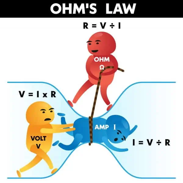
Ohm’s Law
Ohm’s Law is the most basic relationship of circuit analysis in electrical engineering :
V = IR
It defines the relationship between voltage, current, and resistance. Despite its simplicity, it is used in nearly every electrical calculation.
Practical applications include:
- Calculating voltage drops
- Determining current flow
- Designing resistor networks
- Power dissipation estimation
Kirchhoff’s Laws
These Kirchhoff’s laws are essential for analyzing complex circuits.
Kirchhoff’s Current Law (KCL)
The total current entering a node equals the total current leaving the node.
Sum of currents entering = Sum of currents leaving
This law is based on conservation of charge.
Kirchhoff’s Voltage Law (KVL)
The algebraic sum of all voltages in a closed loop equals zero.
Sum of voltages in loop = 0
This law is based on conservation of energy.
Together, KCL and KVL allow analysis of multi-loop and multi-node circuits.
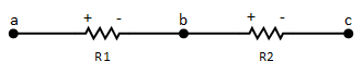
Series and Parallel Circuits
Series Circuits
- The same current flows through all components
- Total resistance is the sum of individual resistances
R_total = R1 + R2 + R3 + …
Parallel Circuits
- Same voltage across all components
- The reciprocal rule applies
1 / Rtotal = 1/R1 + 1/R2 + 1/R3 + …
Understanding series and parallel combinations simplifies many real-world systems.
Network Theorems
Network theorems are powerful tools for simplifying complex circuits.
Thevenin’s Theorem
Any linear circuit can be replaced with an equivalent voltage source in series with a resistance.
Useful for:
- Load analysis
- Maximum power transfer
- Simplifying large networks
Norton’s Theorem
Any linear circuit can be replaced with an equivalent current source in parallel with a resistance.
Superposition Theorem
In linear circuits with multiple sources, analyze each source independently and sum the results.
Maximum Power Transfer Theorem
Maximum power is delivered when load resistance equals source resistance.
These theorems reduce computational complexity significantly.
Nodal Analysis
Nodal analysis uses Kirchhoff’s Current Law to determine node voltages.
Steps:
- Identify reference node (ground).
- Assign node voltages.
- Apply KCL at each node.
- Solve resulting equations.
It is highly efficient for circuits with many parallel branches.
- Charging EV: A Beginner’s Guide to Electric Vehicle Ownership
- 3D Scanning in Industrial Inspection and Engineering Applications
Mesh Analysis
Mesh analysis uses Kirchhoff’s Voltage Law to determine mesh currents.
Steps:
- Identify independent loops.
- Assign mesh currents.
- Apply KVL around each loop.
- Solve equations.
Best suited for planar circuits with fewer nodes.
Star–Delta (Y–Δ) Transformation
Star–Delta transformation is a network conversion technique used to simplify three-terminal resistor networks that cannot be reduced using simple series or parallel combinations.
It allows conversion between:
- Star (Y) configuration
- Delta (Δ) configuration
This method is especially useful in bridge circuits and complex resistor networks.
Why It Is Needed
Sometimes, three resistors are connected in a triangular (Δ) or star (Y) shape, and they are not directly reducible using basic rules.
Instead of applying complex Kirchhoff equations, we convert one form into the other to simplify analysis.
AC Circuit Analysis
In alternating current circuits, analysis includes:
Impedance:
Z = R + jX
Where:
- R = resistance
- X = reactance
- j = imaginary unit
AC analysis introduces frequency-dependent behavior and requires phasor representation.
Transient Analysis
Transient analysis studies circuit behavior during switching events.
Important in:
- Power systems
- Control systems
- Electronics switching circuits
It involves differential equations and exponential responses in RL and RC circuits.
Power Analysis in Circuits
Power evaluation ensures safety and efficiency.
Key concepts:
Real Power (P):
Real power is the actual useful power that performs work. It is measured in Watts (W). This is the power that:
- Turns a motor
- Lights a bulb
- Heats a heater
- Charges a battery
Reactive Power (Q):
Reactive power is the power that is temporarily stored and then returned to the source. It is measured in VAR (Volt-Ampere Reactive).
Reactive power exists because:
In every AC cycle:
Energy is stored → returned → stored → returned
This power does not perform useful work, but it is necessary for the operation of magnetic and electric fields.
Apparent Power (S):
Apparent power is the total power supplied by the source. It is measured in VA (Volt-Ampere).
It represents the combination of real and reactive power. Think of it as: Total electrical demand seen by the generator.
Power Factor
Power Factor = P / S = cosθ
Improving power factor reduces system losses and improves energy efficiency.
Power Triangle (Relationship)
These three powers form a right triangle:
S² = P² + Q²
Where:
- P = horizontal (real power)
- Q = vertical (reactive power)
- S = hypotenuse (apparent power)
- The Complete Solar Energy Guide: Design, and Installation
- Comparison of Microinverter vs String Inverter with optimizer
Practical Applications of Circuit Analysis in Electrical Engineering
Circuit analysis is applied in:
- Power generation systems
- Industrial motor control
- Electronic device design
- Solar energy systems
- Automation and robotics
- Electrical installation safety design
Without proper analysis, systems can overheat, fail, or operate inefficiently.
Common Mistakes in Circuit Analysis
- Ignoring reference polarity
- Incorrect loop direction assumption
- Mixing sign conventions
- Overlooking dependent sources
- Forgetting units
Attention to detail is critical in professional engineering practice.
How to Master Circuit Analysis
- Solve problems daily.
- Practice MCQs for conceptual clarity.
- Use simulation tools (e.g., MATLAB, PSpice).
- Re-derive laws instead of memorizing.
- Connect theory to real equipment and lab experiments.
Consistency builds confidence.
FAQs
It enables engineers to design, evaluate, and troubleshoot electrical systems efficiently.
It depends on the circuit structure. Nodal is efficient for many nodes, mesh for fewer loops.
Yes. Circuit analysis principles are also used in electronics and electrical engineering.
Basic algebra is sufficient initially, but advanced topics involve calculus and complex numbers.
Final Thoughts
Circuit analysis is not just an academic subject. It is a core engineering skill that influences every domain within electrical and electronics engineering. From solving simple resistor networks to designing complex power systems, the principles remain consistent.
Mastering circuit analysis builds analytical thinking, mathematical precision, and professional confidence. With structured learning, regular practice, and practical application, it becomes one of the most rewarding subjects in electrical engineering.
This guide serves as a comprehensive foundation. Continue exploring advanced topics, solve practical problems, and strengthen your understanding through real-world applications.