The alternating current (AC) is different from the Direct current (DC) because of its changing behavior. So, the basic elements of a circuit are expected to behave differently in the AC circuit as compared to the DC circuit. The opposition to the alternating current is called impedance rather than resistance. It can be represented with an impedance triangle. We will learn how to calculate the impedance triangle. The AC source usually provides sinusoidal voltage to the circuit, i.e., mathematically.

Which causes an AC circuit to flow an AC sinusoidal current in the circuit, i.e., mathematically

Where ω is the angular frequency given by the following relation to the frequency

Before knowing how each element responds to the AC sinusoidal source, let me define the difference in impedance, reactance, and resistance.
Difference Between Impedance, Reactance, and Resistance :
Resistance:
Resistance is the friction experienced by the free electron in every conductor except the superconductor. It is denoted by the capital letter “R” and measured in “Ohms”. The frequency does not affect the resistance.
Reactance :
Reactance is inertia because of the motion of electrons, which is present in every current-carrying conductor but is most prominent in inductors and capacitors in AC circuits. Reactance has two types: inductive and capacitive reactance. As the name suggests, the inductor-provided opposition is called inductance reactance, whereas opposition by the capacitor is called capacitive reactance. Both are denoted by the capital letter “X” with a subscript of “L” for the inductor and “C” for the capacitor. It is also measured in “Ohms”. Reactance changes with a change in frequency.
Impedance :
Any opposition to current in an AC circuit is called impedance, which may be provided by any circuit element like a capacitor, inductor, or resistor. The symbol for that is “Z” and the unit for impedance is “Ohm”. This much broader term than resistance and reactance. Impedance can be obtained from the combination of resistance and reactance vector addition. Impedance can also be affected by a change in frequency.

How to Calculate Impedance Triangle
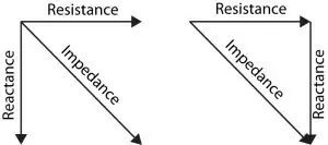
The impedance triangle is the Phasor representation of the impedance of an AC circuit. Resistance is shown on the real axis (x-axis), and reactance is shown on the imaginary axis (y-axis). Their vector addition makes the impedance triangle complete. As the resistance can only be positive, that’s why the triangle always occupies the first and fourth quadrants of the axes.
Using the Pythagoras theorem on the right-angle impedance triangle, we can find the impedance formula, which is given below.
Impedance of Resistor
Suppose the following circuit with an AC source and a resistor. According to Ohm’s law, the voltage and current are linearly related, i.e.
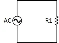

Putting the AC voltage from equation (1) into it will give us

- Charging EV: A Beginner’s Guide to Electric Vehicle Ownership
- 3D Scanning in Industrial Inspection and Engineering Applications
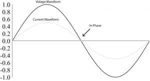
Comparing the voltage and current equations (1) and (2b), we observe that both current and voltage have the same frequency and phase. See the following graph for better comprehension.
Putting the equation (2b) into (2a) will give us

Now, comparing equation (2c) with the following equation

Will give us that

The only opposition to the alternating current is the resistance itself.
Looking at the equation (2d) for the impedance of a resistor, we observe that there is no frequency involvement, so the resistance doesn’t change with a change in frequency.
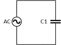
Impedance of a Capacitor
In a pure capacitive AC circuit, the only opposition to the current is the capacitive reactance. According to the capacitor current and voltage relation, the current through the capacitor will only flow if there is a change in the capacitor voltage, i.e.

By putting the AC source voltage from equation (1)

Using some calculus knowledge, we can find the above derivative as follows

Where

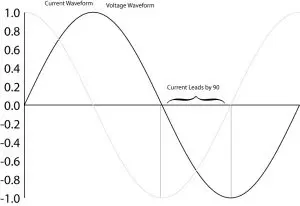
Observing the voltage and current equations (1) and (3a) implies that the current in a purely capacitive circuit is 90o leading from the source voltage. To understand what the statement means, take a look at the following graph.
The reactance of a capacitive circuit can be shown by the following generic equation.

Comparing this generic equation to the specific equation (3b) will show that.

XC is the capacitance reactance, the only opposition to AC in a capacitive network.
Observing equation (3c), we notice that capacitive reactance has an inverse relationship with frequency. By increasing the frequency, the reactance will decrease and vice versa. In the special case of a DC circuit, the capacitor will have infinite impedance, which will cause no current to flow through it. That’s why it is stated that the capacitor is almost open to DC. Whereas for high frequencies the reactance will be too low, that’s why capacitors act short for high-frequency AC.
- Basic Electrician Test – Check Your Electrical Knowledge
- Complete Guide to Circuit Analysis in Electrical Engineering
Impedance of Inductor
In a pure inductor AC circuit, the only opposition provided to the current is by the inductor. The current and voltage relation of an inductor is given by the following equation.

Where the AC is given by the equation

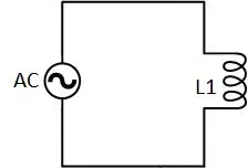
In a pure inductor AC circuit, the only opposition provided to the current is inductive reactance. The current and voltage relation is given by the following equation.

Where the AC is given by the following equation

Putting it into the above equation will give us

Using some calculus knowledge will help us in finding the above derivative as follows.

Where

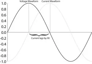
Comparing the voltage and current through the inductor, the current through the inductor lags the source voltage by 90 °. For more comprehension, take a look at the following graph of the current and voltage phase relation of an inductor.
The inductive reactance can be found by comparing equation (4b) with the following generic equation.

Which will give us

Inductive reactance XL is the only opponent in a pure inductive network for AC.
In (4c), the frequency and inductive reactance have a direct relationship with each other; by increasing the frequency, the inductive reactance will increase and vice versa. In the special case of the zero frequency (DC), the reactance will also be zero. Whereas for high-frequency AC, the reactance is high. So, inductors are short for DC and almost open to high-frequency AC.
Conclusion :
- The AC is opposed not only by resistance but also.
- Impedance is the vector combination of resistance and reactance.
- The impedance triangle is the vector representation of impedance, reactance, and resistance.
- In a purely resistive circuit, voltage and current are always in phase with each other.
- In a purely inductive circuit, the current lags by 90 degrees from that of the voltage.
- In a purely capacitive circuit, the current leads by 90 degrees from that of the voltage.
FAQs
Inductive reactance is related to?
Inductive reactance is related to frequency and inductance.
What is inductive reactance measured in?
Inductive reactance is measured in ohms and increases with higher frequencies or larger inductance values.
How to calculate inductive reactance?
To calculate inductive reactance XL, you can use the formula:

Where:
- XL is the inductive reactance in ohms (Ω),
- π is a mathematical constant (approximately 3.14159),
- f is the frequency of the AC signal in hertz (Hz),
- L is the inductance of the coil in henrys (H).
How to calculate the impedance triangle?
The impedance triangle visually represents the relationship between resistance R, inductive reactance XL, and capacitive reactance XC in electrical circuits, aiding in the calculation of total impedance Z.
What does angle theta represent in the impedance triangle?
In the impedance triangle, angle θ represents the phase angle or phase difference between the voltage and current in an AC circuit.