What does it mean by charging and discharging a capacitor? What are the working principles of capacitor charging? What is the capacitor charging and discharging theory?
Charging a capacitor means the accumulation of charge over the plates of the capacitor, whereas discharging is the release of charges from the capacitor plates. The transient response of capacitor charging and discharging is governed by ohm’s law, voltage law, and the basic definition of capacitance.
- Top 5 Essential Electrical Wiring Rules to Follow for Your Home
- Breaker Size Calculator: AC and DC Circuit Breaker Sizing Calculator
Capacitor Charging:
Suppose we have the circuit below, with capacitor C, voltage source V and a toggle switch. Consider the capacitor is discharged initially and the switch is open. At some point in time, I move the switch to position 1, and let’s say that time is t=0.
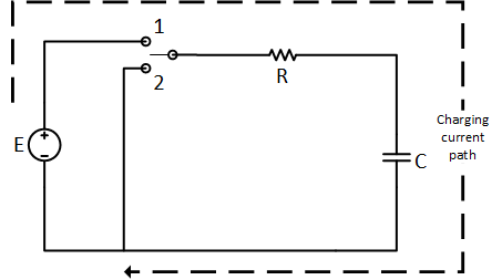
Charging Current of the Capacitor:
At time t=0, both plates of the capacitor are neutral and can absorb or provide charge (electrons). By closing the switch at time t=0, a plate connects to the positive terminal and another to the negative. The plate of the capacitor connected to the positive terminal provides electrons because the plate has comparatively more electrons than the source positive terminal. And plate connected to the negative terminal absorbs electrons provided by the source negative terminal which has comparatively more electrons. This movement of the electrons is the charging current during the charging phase.
The voltage across the Capacitor:
At time t=0, the voltage across the capacitor plates is “absolutely zero”. As electrons start moving between source terminals and capacitor plates, the capacitor starts storing charge. The phenomenon causes a huge current at the moment when the switch is closed at time t=0. As charge stores, the voltage across the capacitor rises and the current between source and capacitor goes down. At some stage in the time, the capacitor voltage and source voltage become equal, and practically there is no current flowing. The duration required for that “no-current situation” is a 5-time constant ($5\tau $). In this state, the capacitor is called a charged capacitor.
Capacitor Charging Equation
Current Equation:
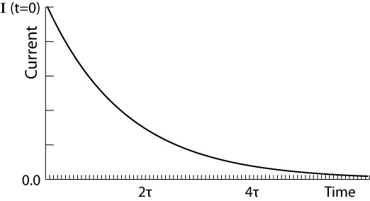
The below diagram shows the current flowing through the capacitor on the time plot. Current flowing at the time when the switch is closed, i.e. t=0 is:
$i(t=0)=i_{R}=i_{c}=\frac{E}{R}$
Where instantaneous current can be found using the following formula:
$i_{c}=\frac{E}{R}e^{-\frac{t}{RC}} $
Voltage Equation:
The below diagram shows the voltage across the capacitor and resistor on the time plot. The following formulas are for finding the voltage across the capacitor and resistor at the time when the switch is closed i.e. at t=0:
$v_{c}(t=0)=0$
$v_{R}(t=0)=E$
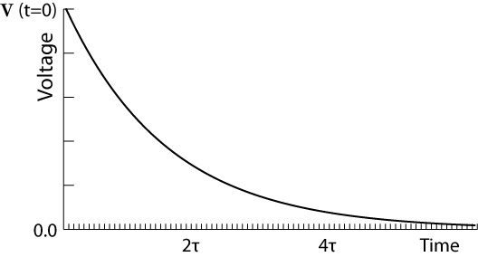
The formula for finding instantaneous capacitor and resistor voltage is:
$v_{c}=E (1-e^{-\frac{t}{RC}})$
$v_{R}=Ee^{-\frac{t}{RC}}$
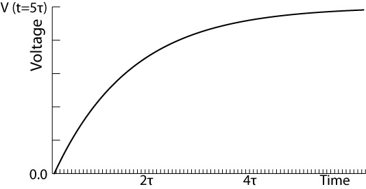
RC Time Constant:
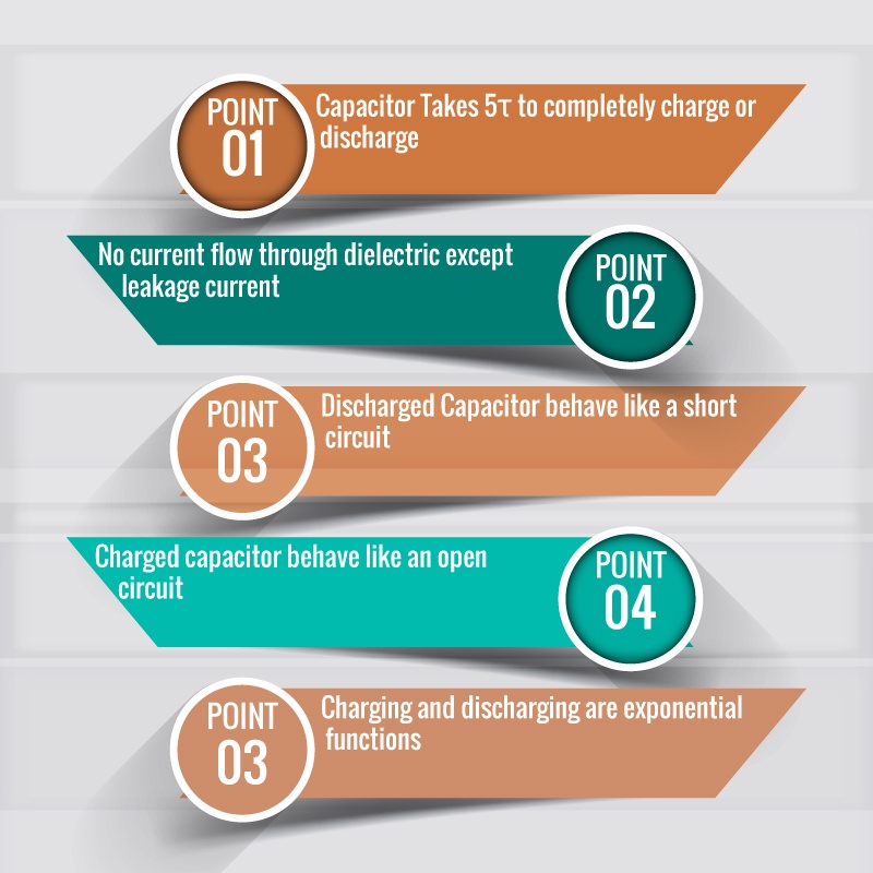
Here R and C are replaced with the Greek letter $\tau $ (Tau) and named as “RC time constant” measured in seconds. The capacitor takes $5\tau $ seconds to fully charge from an uncharged state to whatever the source voltage is.
RC Time Constant = $5\tau$
Current and Voltage Equation:
The current across the capacitor depends upon the change in voltage across the capacitor. If there is a changing voltage across it, will draw current but when a voltage is steady there will be no current through the capacitor. That’s why it draws current for only a small amount of time during charging.
${ i }_{ c }=C\frac { d }{ dt } ({ V }_{ c })$
Capacitor Charging Summary :
- At the instant when the switch was closed, the capacitor draws a very large current that behaves like a short circuit. At that moment almost zero voltage appears across the capacitor. Current in the circuit is only limited by the resistance involved in the circuit.
- When charging time ends, the capacitor behaves like an open circuit and there is no current flowing through the capacitor and has a maximum voltage across it.
Capacitor Discharging:
Suppose the capacitor shown below is charged by a voltage source E, so the voltage across the capacitor will be raised to voltage E. Now I move the switch to position 2 in the following circuit, the capacitor is connected to resistive load instead of the voltage source. The capacitor will now work as a source for the resistor and voltage across the capacitor will start to lose its stored charge bypassing current. By losing the charge, the capacitor voltage will start to decrease. For a constant resistor, the current will also start to reduce as voltage decreases. Finally, the voltage across the capacitor will hit the zero point at a 5-time constant ($5\tau $). Similarly, the current will also go to zero after the same time duration.
- Differences Between Fixed Wiring Testing and PAT Testing
- Sustainability in Flex: Green Practices in Flexible PCB Manufacturing
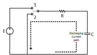
Capacitor Discharge Equation:
To find the voltage and current of the capacitor at any instant, use the following capacitor discharging equation:
$v_{c}=Ee^{-\frac{t}{RC}}$
$i_{c}=\frac{E}{R}e^{-\frac{t}{RC}}$
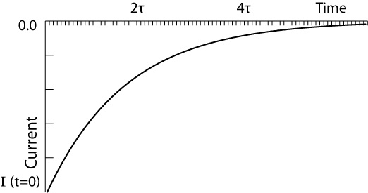
Notice the above graph is below the zero lines because the direction of current flow during discharging phase is opposite to that of the charging phase.

As the resistor and capacitor are connected in series, so the current is the same for both. Where voltage across the resistor is different and represented by the following formula:
$v_{R}=Ee^{-\frac{t}{RC}}$
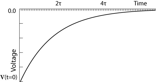
The discharging is also dependent upon resistance and capacitance and takes to completely discharge.
- Elevate Your Boating Experience with a Marine SoundBar
- Efficient Travel Refrigerator for Cars: A Complete Guide
Initial Condition:
In all the above discussion, we suppose an uncharged capacitor, however, it may not always be the case. Here we are interested in charging a capacitor that has already some charge stored on it. Because of the charge stored, the capacitor would have some voltage across it i.e.
$v_{i}=\frac{Q_{i}}{C}$
$Q_{i}$ is the initial charge stored on capacitor terminals which causes the initial voltage on its terminals $v_{i}$.
Now we are connecting the above capacitor to a circuit with source voltage E. There will be a difference between the source voltage and capacitor voltage, so the capacitor will start to charge and draw current according to the difference in voltage. The capacitor voltage will increase exponentially to the source voltage in 5-time contents.
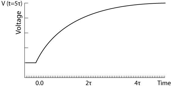
The graph above shows the voltage across the capacitor. The initial voltage is represented by the flat portion of the graph. And the charging phase is represented by the curve portion of the graph.
Find the transient voltage across the capacitor using the following formula:
$v_{f}=v_{i}+(v_{f}-v_{i})(1-e^{-(\frac{t}{\tau })})$
V$_{f}$ is the voltage of the source, and V$_{i}$ is the voltage of the charged capacitor before connecting to the circuit.
Conclusion :
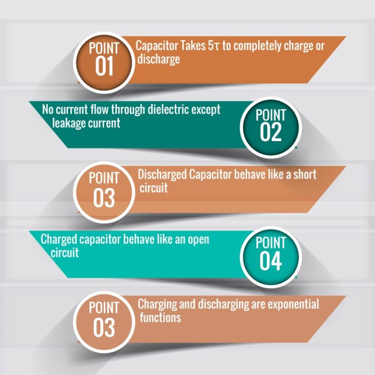
- No current flows through the dielectric during the charging and discharging phase except leakage current.
- It takes 5 times constant to charge or discharge a capacitor even if it is already somewhat charged.
- The capacitor voltage exponentially rises to source voltage where current exponentially decays down to zero in the charging phase.
- As the switch closes, the charging current causes a high surge current which can only be limited by the series
- A discharged capacitor behaves like a short circuit when initially connected to the circuit, which means causing a surge current initially.
- A capacitor behaves like an open circuit when it is fully charged, which means not allowing current through it.
- In the discharging phase, the voltage and current both exponentially decay down to zero.
Thank you for this article. It was well written and explained what I wanted to know (I previously thought that electrons were travelling through the dielectric during a discharge).
It would be interesting to know how a capacitor stores in a AC circuit. Since there is no electric switch in a real circuit, how can the capacitor still store charge?
As the AC source changes its polarity after each half cycle, that why the capacitor charges in the first half cycle and discharges in another half cycle. Rather than consuming power, the power flow back and furth in AC capacitive circuit.
Why the time constant during discharging of capacitor greater than charging in my experiment?
It is possible that may be the circuit you are using to charge and diacharge has different resistance and thus their time constants are different.