Learn what Kirchhoff’s voltage law is and how to apply it with examples. Kirchhoff’s voltage law, KVL or Kirchhoff’s second law, deals with the conservation of energy in a closed-loop electric circuit. The KVL is the fundamental law for electrical circuit analysis.
What does Kirchhoff’s Voltage Law state?
The Kirchhoff Voltage Law KVL states that the algebraic sum of the voltage produced and the voltage dropped in a closed loop (a closed path) of an electric circuit is always equal.
- Charging EV: A Beginner’s Guide to Electric Vehicle Ownership
- 3D Scanning in Industrial Inspection and Engineering Applications
Mathematically,

In other words, the energy is conserved across a closed loop of an electric circuit.
Note that the algebraic sum means taking into account the polarities and signs of voltage sources and voltage drops. When applying the KVL to any circuit, all the signs (+ -) or (- +) must be taken into account correctly, the calculation will be wrong.
- Basic Electrician Test – Check Your Electrical Knowledge
- Complete Guide to Circuit Analysis in Electrical Engineering
Gustav Kirchhoff, a German physicist, presented two laws: Kirchhoff’s Current Law (KCL) and Kirchhoff’s Voltage Law (KVL). Ohm’s law is very basic, which may not be sufficient to analyze a complex circuit. Kirchhoff’s Voltage Law KVL provides the basis for Mesh Current Analysis.
How to apply Kirchhoff’s Voltage Law
Identify closed loops
Identify closed loops in an electric circuit and assign a loop name to each closed loop. Suppose a loop current is in a certain direction.
Identify current direction
Now, caption each circuit element with a polarity sign as follows, according to the supposed current direction.
Apply KCL
Apply Kirchhoff’s Current Law KCL at each node and write current equations for each node.
Write the KVL equation.
Now apply KVL at each closed loop and write the equation for each loop. All the voltage produced should be equal to all the voltage drops.
Combine equations
Now substitute the KCL equations in the KVL equations to get the final equations. Solve those equations using any of the solvers.

Kirchhoff’s Voltage Law Example
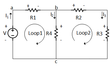
Suppose a circuit with two parallel paths (loops) and a single voltage source (DC), as shown in the diagram below. Find the current and voltage of each element of the circuit for the following given circuit parameter using Kirchhoff’s voltage law.
R1 = 5Ω
R2 = 10Ω
R3 = 5Ω
R4 = 10Ω
V = 20Volts
- Charging EV: A Beginner’s Guide to Electric Vehicle Ownership
- 3D Scanning in Industrial Inspection and Engineering Applications
KVL Solution:
Assign Loops Name:
There are two loops (closed paths) in the circuit: loop 1 with two resistors and a single voltage source, whereas in loop 2, there is no voltage source, only three resistors.
Assign Sign to Circuit Elements:
Now, assign a positive sign to the resistor terminal that is closer to the voltage source’s positive terminal, and a negative sign to those that are closer to the negative terminal. OR you may assign a (+ -) sign to each component terminal by going through the loop. But make sure that the sign of voltage rise (- +) is exactly opposite to the sign of voltage drop (+ -). Both will give you the same results, even the same equations.
Assign Current Names:
Assign a name to the current of each loop, and as discussed in KCL, write equations for the current at each node. For the above circuit KCL equations will be:

Write Loop Equations:
The next step is to write equations for each loop. Based on the sign and current name assigned, as shown below.
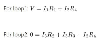
Notice the negative sign in the second equation; it is because of being opposite in the direction of the loop arrow, i.e., for R2 and R3 it is (+ -), but for R4 it is (- +).
Now, put the value of I1, which will give you two simultaneous equations with unknown variables I2 and I3. The value of these currents can easily be obtained using Cramer’s rule for the matrix.

Let’s put the values of the resistors and the voltage source, and see what happens
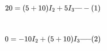
Now multiply equation (1) by -3 and add it to equation (2)

- 10 Lighting DIY LED Projects Ideas for Fun and Entertainment
- 4 Tips for Buying Industrial Equipment for Your Business
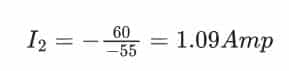
Solve The Equations:
Adding the above two equations will give us equation (3)

OR
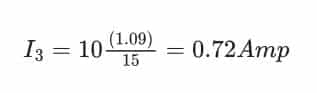
Now putting the current I2in the equation (2) to get the current I3
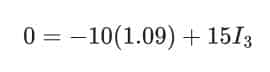
OR
By applying KCL to node b, the following equation can be obtained

Now, putting the values of the current will give us the value of I1

Now, it is easy to find any parameter of the circuit; just use Ohm’s law, as shown below
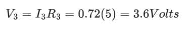
And

Does Kirchhoff’s voltage law apply to parallel circuits?
Yes, KVL law applies to the parallel circuit. First, identify the loops and apply the KVL. The circuit in the above example is a parallel circuit.
Kirchhoff’s Voltage Law Limitation:
The KVL has some practical limitations, but it is a very useful tool for circuit analysis.
- In the high-frequency circuit, the fluctuating magnetic field can link the circuit, which contradicts the assumption of KVL.
Short Answer Questions:
Can Kirchhoff’s voltage law be applied to an incomplete loop?
Kirchhoff’s second law must be that the loop is closed. The open loop will not allow the current to flow, and there will be no voltage drop across the circuit elements. All the voltage in the loop will appear across the open portion.
What is a parallel circuit?
A parallel circuit is an electrical arrangement where components are connected side by side, allowing multiple paths for current flow. Voltage across components remains constant, while current divides among them.
Does Kirchhoff’s voltage law apply to parallel circuits?
Yes, Kirchhoff’s Voltage Law applies to parallel circuits. It states that the sum of the voltages across all components in any closed loop within the circuit is zero.