Power Factor and Average Power in an AC circuit Explained with Power Triangle

The average power of DC is different from the average power in an AC circuit. The alternating current uses sinusoidal voltage and current, which change its direction and magnitude every moment. How could one say that the power in an AC circuit has a fixed value?

Average power in an ac circuit

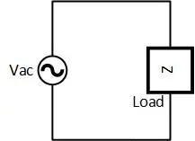
Suppose a general load is connected with an AC source, as presented in the diagram. Suppose it has a voltage

$v=V_{m}sin \omega t\ldots (1a)$

Which causes it to flow the following sinusoidal current

$i=I_{m}sin \omega t+\theta \ldots (1b)$

The power flow of the source will be

$p=vi=(V_{m}sin \omega t)(I_{m}sin \omega t+\theta )$

$p=V_{m}I_{m} sin \omega t.sin \omega t+\theta \ldots (1c)$

Using the following trigonometric identity

$sin A .sin B=\frac{1}{2}cos (A-B)-\frac{1}{2}cos (A+B)$

so

$p=\frac{V_{m}I_{m}}{2} [cos (\omega t-\omega t-\theta )-cos (\omega
t+\omega t+\theta )]$

As we know from the following trigonometric identity that

$cos \theta =cos -\theta $

Now

$p=\frac{V_{m}I_{m}}{2}cos \theta -\frac{V_{m}I_{m}}{2}cos (2\omega
t+\theta )$

Now observe the above equation, the power is made up of two cosine terms. The second term frequency is twice ($2 \omega t)$. As that of current or voltage (both have the same frequency of $\omega t$). This term has a component of time in it, which causes the cosine wave to oscillate and its average value over a cycle is zero. That’s why no energy is transferred due to the second term to the generic load attached to the AC source. Energy only floats back and forth between load and source.

Where the first term has no element of time, so it gives a fixed value for a specific value of theta. This is called the average power dissipated in the load. This average power in an AC circuit is mostly called real or active power. This power depends upon the angle $\theta $, which is the phase difference between current and voltage. So the equation for the real power is

$P=\frac{V_{m}I_{m}}{2}cos \theta$
$=\frac{V_{m}}{\sqrt{2}}\frac{I_{m}}{\sqrt{2}}cos \theta $

Where the relationship between RMS and peak value is $V_{RMS}=\frac{V_{m}}{\sqrt{2}}$, putting it into the above equation will give us

$P=VIcos \theta \ldots (1d)$

average Power in an ac circuit with pure resistive load

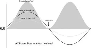
In a purely resistive AC circuit, the circuit current and voltage are in-phase, or the phase difference angle is zero i.e. $\theta =0 ^{\circ}$. So, the average power in an AC circuit with pure resistive load will

$P=VIcos 0^{\circ}$

$P=VI (1)cos 0^{\circ}=1$

$P=VI\ldots (2a)$

The equation (2a) means that the power delivered to the load is maximum in a purely resistive circuit.

Where in pure inductive AC load, the load current lags by $90^{\circ}$, i.e. $\theta ^{\circ}=-90^{\circ}$. So, the average power in an AC circuit with an inductive load will be

average Power in an ac circuit with pure inductive load

$P=VIcos (-90^{\circ})$

$P=VI (0)cos -90^{\circ}=0$

$P=0\ldots (2b)$

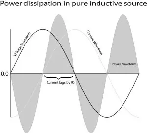
Equation (2b) means that no power is dissipated in a purely inductive load, the power only floats back and forth between the inductive load and the source.

In a pure capacitive AC circuit, the current leads source voltage by $90^{\circ}$ i.e. $theta =90^{\circ}$. In this case, the average power in an AC circuit with pure capacitive load is

average Power in an ac circuit with  in pure capacitive load

$P=VIcos 90^{\circ}$

$P=VI (0)cos 90=0$

$P=0\ldots (2c)$

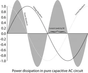
According to equation (2c), the power dissipated by the pure capacitor circuit is zero. Power only floats back and forth between the source and the capacitive load.

What is the Power Factor and Why is it Important?

We have seen in the above section that power dissipation depends upon the cosine of the phase angle along with the amplitude of voltage and current. For example, if the phase angle is 90 no power will dissipate, and if it is zero or somewhere between themes the load will dissipate power. The cosine term is very important and is called the power factor (PF).

$Power Factor=cos \theta \ldots (3a)$

Wherefrom impedance triangle we can calculate it through the following formula

$cos \theta =\frac{R}{Z}$

And from the power triangle, we can find like

$cos \theta =\frac{P}{S}$

According to equation (3a), the maximum power factor can be ONE and the minimum PF can be ZERO. An AC circuit containing multiple elements like a resistor, inductor, and capacitor can have a power factor between zero and one.

The power factor has no unit but it is usually expressed as a leading or lagging power factor. The leading/lagging depends upon the phase relationship between current and voltage. If the current leads the voltage, the power factor is called leading, and if the current lags, the power factor is called the lagging power factor. The PF of a capacitive circuit is leading and that for an inductive circuit is lagging.

Why is the Power Factor Important?

The power factor in an AC circuit helps us in finding how much energy is utilized for performing the desired work. For the power factor equal to one or the “Unity power factor“, the total power is utilized.

Power Factor Visualization


A power factor of less than one causes over-current and voltage drop because of power flow back and forth. Which ultimately increases the initial and running cost of a power generation, distribution, and utilization system. To fulfill the desire over-current desire, the supply company needs more generation units. Supply companies impose a fine on the power factor below a threshold.

What is Active, Reactive, and Apparent Power :

Apparent Power:

Apparent power is a multiplication of the RMS voltage and current without taking the power factor into account. This apparent power is a combination of the power dissipated in load and the power floating back and forth. This power is denoted with “S” and its unit is volt-ampere (VA).

$S= VI$

Reactive Power:

Reactive power is the portion of apparent power that does not perform any work but only goes back and forth between load and source. This power causes undesired current flow and voltage drop. The inductive and capacitive load consists of such types of power. This power is denoted by “Q” and expressed in volt-ampere-reactive (VAR).

$Q=VIsin \theta $

Active Power:

Active power is the portion of apparent power that performs the actual work. That’s why it’s called real or actual power. The power is represented with “P” and expressed in watts. Resistive load consumes active power.

$P=VIcos \theta $

Power Triangle in an AC circuit:

Just like the impedance triangle, the power triangle relates all three types of power to each other. The active or real power, which is consumed by the resistive load, is shown by a vector along the real axis. The reactive power, which is consumed by the inductive or capacitive load is shown by a vector along the imaginary axis. The apparent power is the vector summation of both actual and reactive power.

active reactive and apparent power

The horizontal and vertical components of the apparent power $S=VI=I^{2}Z$ are

Horizontal component, Real power: $P=VIcos \theta =I^{2}R$

Vertical component, Reactive power: $Q=VIsin \theta =I^{2}(X_{L}sin X_{C})$

Power Factor and Average Power in an AC Circuit Example:

Suppose the following AC circuit with resistor and inductor and find the impedance and reactance. Also find the active, reactive, and apparent power of the circuit. Draw the impedance and power triangle for the circuit.

The importance of power is explained with an example ac circuit

First of all, I will find the reactance

$X_{L}=2\pi fL=2\times 3.14\times 50\times 0.156$

$X_{L}=49 \Omega $

Where the resistance is

$R=48\Omega $

Now find the impedance with the following formula

$Z=\sqrt{R^{2}+X_{L}^{2 } }=\sqrt{48^{2}+49^{2}}$

$Z=\sqrt{4705}=68.6\Omega $

Before proceeding to power calculation, I calculate the power factor

$cos \theta =\frac{R}{Z}=\frac{48}{68.6}=0.7 lagging$

The phase angle between current and voltage is

$\theta =cos ^{-1}(\frac{R}{Z})=cos ^{-1}(\frac{48}{68.6})$

$\theta =45.6^{\circ}$

Here the power factor is lagging because of the use of the inductor in the circuit. Now I will calculate the apparent power

$S=VI=V(\frac{V}{Z})=\frac{V^{2}}{Z}$

$S=\frac{262^{2}}{68.6}=1000 VA$

And now actual power:

$P=VIcos \theta =(VI)cos \theta =Scos \theta $

$P=1000\times 0.7=700 watts$

Reactive power:

$Q=VIsin \theta =Ssin \theta $

$Q=1000\times sin 45.6^{\circ}=1000\times 0.71$

$Q=710 VAR$

The example is completed but now let me confirm if did the calculation correctly or not

$S=\sqrt{700^{2}+710^{2}}\approx 1000$

$1000=1000$

So, my calculation is correct.

Conclusion :

  1. Only resistive load dissipates average power in an AC circuit, reactive power only causes undesired current and voltage drop.
  2. The power factor of a resistive load is maximum (one), where inductive and capacitive load PF is minimum (zero) lagging and leading respectively.
  3. Lower power factor arises in some undesired situations like current overloading on the circuit.
  4. PF plays an important role in power dissipation in load. The higher the power factor the more power is consumed in load.
  5. The power triangle consists of real, reactive, and apparent power making the base, perpendicular, and hypotenuse of the triangle respectively.   

1 thought on “Power Factor and Average Power in an AC circuit Explained with Power Triangle”

  1. It’s remarkable to visit this web page and reading the
    views of all colleagues about this post, while I am also eager of getting experience.

    Reply

Leave a Comment

This site uses Akismet to reduce spam. Learn how your comment data is processed.