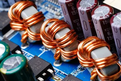
Practically, the inductor has some resistive factor, which is very minute and is ignored. It is represented by a series resistor and inductor and is referred to as RL Circuit analysis. Suppose the following RL circuit, where a toggle switch can connect and disconnect to the circuit source. The voltage across gradually changes according to exponential equations while the inductor is charging and discharging.
Inductor Charging and Discharging in an RL Circuit:
Inductor Charging Phase:
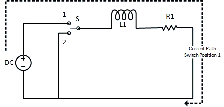
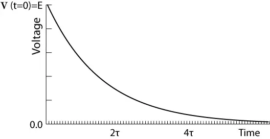
Suppose the inductor has no energy stored initially. At some point in time, the switch is moved to position 1; the moment is called time t=0. As the switch closes, the source voltage will appear across the inductor and will try to pass current (I=V/R) abruptly through the inductor. However, according to the Lenz Law, the inductor will oppose the change in current. The current will gradually increase unless it reaches its final value of current (I=V/R). At the same time, the voltage across the inductor will decrease unless it reaches zero.

- 10 Lighting DIY LED Projects Ideas for Fun and Entertainment
- 100 Watt Inverter: Everything You Need to Know
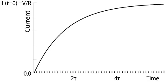
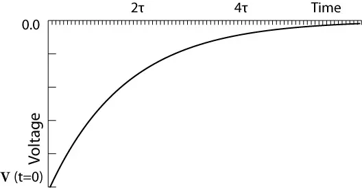
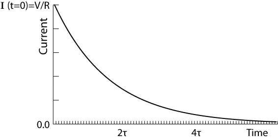
It’s worth mentioning that the current reaches its final value at 5τ, and the voltage reaches that time. The graph of current and voltage transients is shown below.
Inductor discharging Phase in the RL circuit:
Suppose the above inductor is charged (has stored energy in the magnetic field around it) and has been disconnected from the voltage source. Now connected to the resistive load, i.e., the switch is moved to position 2 at the time t=0. The energy stored will be discharged to a resistive load and will be dissipated in the resistor. The current will continue to flow in the same direction and will gradually decrease to zero, as well as the voltage across the inductor. But if the inductor is disconnected and not connected to any load, the current will stop abruptly because of no closed path. According to the equations above, it will cause a huge voltage across the inductor, and you will observe it as a spark at the switch terminals. The same phenomenon is used for car engine ignition.

How does an inductor charge and discharge through an AC power supply?
Inductor charge for half-cycle up to the peak voltage. When the first cycle ends, the inductor starts to discharge. After the complete discharge, the inductor starts to charge in the opposite polarity. For the third half-cycle, similarly, the inductor first discharges and then charges in the opposite voltage polarity. The process continues, and the inductor floats current back and forth rather than consuming the actual power.
- Charging EV: A Beginner’s Guide to Electric Vehicle Ownership
- 3D Scanning in Industrial Inspection and Engineering Applications
How to determine if an inductor is charging or discharging?
If the inductor is taking the current from the source, the inductor is charging. If the inductor provides current to the load, the inductor is discharging. The current can be determined by using Kirchhoff’s Current Law at any load.
Conclusion
The above discussion showed the following key points in detail.
- The inductor doesn’t dissipate energy; it only stores it.
- The inductor changes current gradually rather than abruptly.
- The inductor reaches maximum or minimum voltage and current in just five time constants.
- An inductor behaves like a short circuit in the DC network after five time constants.
- The inductor provides zero resistance after five time constants.
Hey there… I have a small confusion regarding the discharging of the inductor. I was wondering about the polarity of voltage across inductor while discharging. Why is it’s polarity negative?
As an inductor works as a load during the charging phase and works source in the discharging phase. And the direction of the current flow in inductor remains the same. Therefore the direction voltage across the inductor changes as per the KVL.
Nice article
..in the charging diagram the current direction is taken as clockwise but in the discharging one it’s taken anticlockwise …can u pls explain?
Thanks for correction,
Dear Guatam, it is a mistake. Take a look at the the current graph of the inductor it is above the zero line in both cases. And it shows that current direction is same in both cases.
Inductor are strongly charged device or not
What do you mean by strongly charged device?