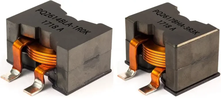
An inductor is a passive circuit element that stores energy in the form of a magnetic field. Inductors are made of wrapped conducting wires or coils, to enhance the effectiveness of the inductor number of turns is increased. The inductance of an inductor increases with the number of turns. An inductor is not anticipated to dissipate energy; it only stores energy and then delivers it to the circuit when required. If the current is passed through it, the voltage across the inductor will change gradually.
The inductance of an inductor
In the 1800’s, Oersted showed that a current-carrying conductor produces a magnetic field around it. When he was conducting some experiments, a compass present near the current-carrying conductor deflected the needles.
After a few years, Ampere showed by doing some careful experiments that the magnitude of magnetic flux is directly related to the amount of current flowing through it.
- Charging EV: A Beginner’s Guide to Electric Vehicle Ownership
- 3D Scanning in Industrial Inspection and Engineering Applications
Michal Faraday and Joseph Henry discovered that a changing magnetic field can produce a voltage across its neighboring circuits. They also showed that the magnitude of voltage is dependent on the rate of change of flux.

The letter “L” is the symbol for the inductance of an inductor.
Inductance is the measure of the property of an inductor that opposes the change in current flow.
If a current is passed through an inductor, the voltage across the inductor changes gradually rather than abruptly. It can be represented mathematically.
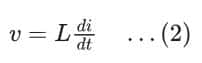
From equation (2), it can be implied that if there is a constant current flowing through the inductor, the voltage across the inductor will be zero. It means that an inductor will act as a short circuit for the DC power supply.
An inductor acts like a short circuit to a DC source.
According to equation (2), a discontinuous change in inductor current needs an infinite voltage across the inductor, which is practically impossible. So the inductor opposes a change in current, either a positive change or a negative change, explained by the Lenz Law.
Lenz Law:
The Lenz Law states that the direction of the induced voltage is always such that it opposes its cause, which produces it. As discussed earlier, the magnetic flux is directly related to the current flowing through it. So, when the current increases, the flux also increases; this change in flux causes a voltage to be induced in such a direction that opposes the existing current. Similarly, when current and flux decrease, it causes the voltage to be induced in such a direction that opposes the existing current. This is “choking,” and that’s why inductors are named chokes.
The inductance of an Inductor :
The inductance of an inductor can be found using the following formula:

- Charging EV: A Beginner’s Guide to Electric Vehicle Ownership
- 3D Scanning in Industrial Inspection and Engineering Applications
Where N is the number of turns in the coil, A is the cross-sectional area of the wire, l is the length, and μ is the permeability of the core through which magnetic flux passes. The permeability depends upon the material used and varies from material to material. Just like capacitors and resistors, the inductor is also available in the market from a few micro-Henry to tens of Henry, which may be fixed or variable.
Energy Stored in Inductor:
The inductor works like a capacitor and doesn’t dissipate energy. It stores electric energy in the form of a magnetic field during the charging phase and releases the same energy to the circuit in the decay phase. Energy stored in the inductor is the product of current through the inductor and voltage across the inductor.
The inductor absorbs power and is

From equation (2), we know that

Putting it into the above equation

Where stored energy can be found by integrating both sides up to the charging time

If the inductor is initially not charged or left unconnected for a long time, then the initial current i(t0) will be zero. Thus, the following formula is applicable for finding stored energy.

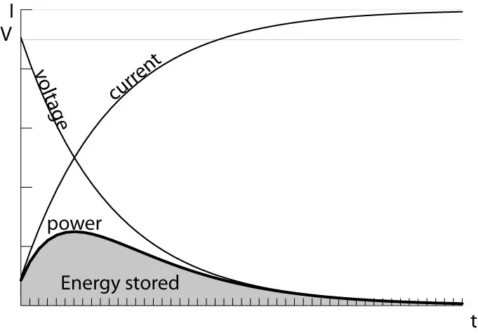
The energy stored is represented by the graph below.
What is the Maximum Energy Stored in an Inductor?
Look at the above graph, and you will understand the maximum energy storage in an inductor. The graph has current, voltage, and power lines. It has also told us about the energy stored in an inductor by the shaded area. The energy is stored in the area under the power curve. And this could be maximum if the power of the inductor goes to zero. Or the current or voltage of the inductor goes to zero. As the exponential decay or rise, it theoretically tends to infinity. But practically, when it consumes the time of 5 τ.
If you want to increase the energy stored in an inductor, increase the inductance of the inductor and the current through it. This can be seen in the energy storage formula, as these parameters are directly related.
Inductor Construction :
The basic construction of an inductor contains an insulated (enameled) wire wound. The winding may be supported by a core or not. In the case of not being supported by an internal core, it is similar to an air-core inductor. In another case, the winding is supported by an iron core, which is an iron core inductor. Iron is a ferromagnetic, highly permeable material that provides a low reluctance path for the magnetic flux. It also confines the magnetic flux near the winding and increases the flux linkage. At low frequencies, the core is made of thin plates called laminations to reduce eddy current losses. For high frequencies, the core is made of soft ferrite so as not produce high eddy current losses.
- Basic Electrician Test – Check Your Electrical Knowledge
- Complete Guide to Circuit Analysis in Electrical Engineering
Eddy Current Losses :
The core inside the inductor is subjected to the magnetic flux of the inductor. Upon variation in the flux, the iron core behaves like a conductor, and a voltage is induced inside the core. The induced voltage causes a current inside the core, which is named the Eddy current. The current increases losses by producing heat.
To counter the eddy current losses, the core is made of laminations, the iron thin plates insulated from each other. Thus, the flow of current is limited by increasing the resistance in the current path.
Q Factor of Inductor :
Practically, the inductor shows some resistance, which absorbs part of the apparent power and reduces the efficiency of the inductor. Q Factor is the measure of the efficiency of the inductor at the given frequency and is equal to the ratio of inductive reactance to the resistance. The higher the Q factor, the nearer it is to the ideal inductor and the narrower the bandwidth in a resonant circuit. The radio uses a high-Q factor inductor with a capacitor to make the circuit resonant.

The voltage across the Inductor in Series:
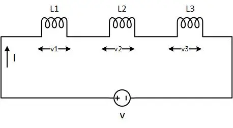
Just like resistors and capacitors, inductors are combined in series and/or parallel. We are interested in finding the equivalent inductance of the combination. If there is only one path for the current, the combination of inductors will be a series combination, as shown in the diagram below.
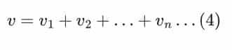
Applying the KVL to the circuit above
The voltage across the inductor depends on changes in the current

We know that there is only one path for current, so the current for all elements is the same
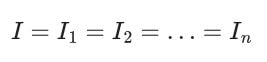
Now put it into the above equation (4)

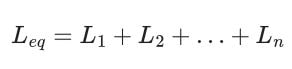
So, equivalent inductance in series is
Inductors in Series-Parallel Calculator :
The voltage across the Inductor in parallel :
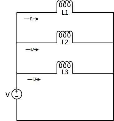
If multiple inductors are connected such that there are multiple paths for current to flow, such a combination is a parallel combination. Now, consider the following parallel combination of inductors shown in the diagram.
Now, applying KCL to the above diagram will give us the following equation
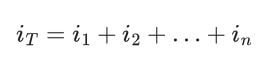
We know that voltages are the same in a parallel combination, so putting that into the above equation
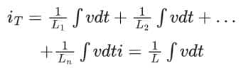
OR

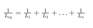
So equivalent inductance in the case of the parallel combination will be
Conclusion :
- Inductors are passive electrical components that store energy in the form of a magnetic field.
- Inductors resist change in current, and they are commonly used in electronic circuits to avoid current surges.
- The inductance of an inductor increases in series and reduces in parallel.
FAQs
Which of the following graphs depicts the voltage across the inductor?
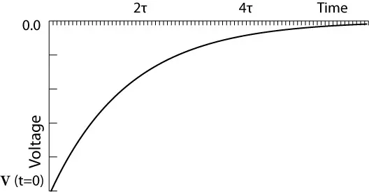
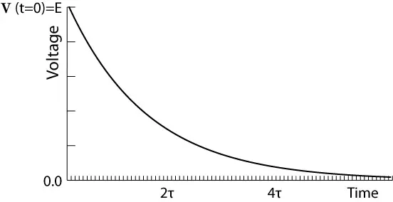
The answer is that both of the graphs depict the voltage across the inductor. Graph A depicts the discharging phase, and Graph B depicts the charging phase.
How to calculate the voltage across parallel inductors?
To calculate the voltage across the parallel inductors, use the following formula for n inductors and their voltages.

What is the phase angle between the voltages of the inductor and capacitor in an RLC series circuit?
The phase angle between the voltage and current of the inductor and the capacitor voltage in an RLC series circuit is 180 degrees.