An alternating current waveform has a specific frequency. When comparing it with another AC quantity (AC voltage, current, power, etc.), an effect of leading or lagging can be seen in the time domain waveform. The time-domain representation of different waveforms can be more intuitive but tedious in the case of multiple AC quantities and more data operations. To work with a large number of AC parameters waveforms, a simple representation can be introduced to differentiate their magnitude and phase angle is called the Phasor Representation of AC circuit analysis. Phasor arithmetic follows the rules of phasor algebra.
The phasor representation of an AC quantity is a counter-clockwise rotating vector originating from the origin of the XY-axes (zero points) in a specific direction. The direction of the phasor shows the angle of a sinusoidal waveform when it passes through the vertical axis.
The magnitude of the phasor represents the magnitude of the quantity, and the angle with the X-axis shows the phase angle. The phasors are used while comparing and performing mathematical operations on AC quantities. Remember that phasors are used only when the frequency is the same.
Difference between Phasor and vector :
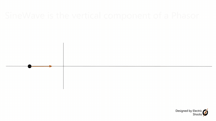
Before going further, let me clear the confusion between vector and phasor. Vectors are stationary, making a certain angle with the real axis. Where phasor is a radius-vector of a circle that rotates anti-clockwise. The phasor direction shows the initial position of the rotation. If the only vertical component of a phasor is drawn against angle or time, you will get a sine wave, and for the horizontal component, you will get a cosine wave.
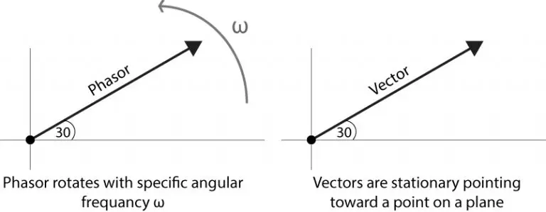
A phasor contains information about the magnitude, phase angle, and angular frequency. Where vector tells us about magnitude and direction rather than the phase angle. Vector is a stationary and broad term for directional quantities. In contrast, a phasor is a specific term referring to anti-clockwise rotational vectors.
Need for Phasor Algebra in AC Circuit Analysis :
While comparing two different waveforms in an AC circuit analysis, i.e., current and voltage. It is possible to draw them on the same set of axes and visually analyze the difference between them. This could be a very tedious and lengthy process with limited accuracy.
Similarly, while operating multiplication, addition, and many more, it is possible to perform the operation point by point. Again very lengthy, exhaustive, and time-consuming process with less accuracy. These collective operations are phasor algebra operations.
Relationship between Phasor and Sinusoidal:
Suppose a vector rotating counterclockwise with an angular frequency of ω radians/seconds. If the vertical component (Y-part) of the vector is plotted step-by-step as the vector moves, the plot will be a sinusoidal waveform.
- Charging EV: A Beginner’s Guide to Electric Vehicle Ownership
- 3D Scanning in Industrial Inspection and Engineering Applications
For a unit circle, when the vector is making zero degrees with the x-axis, the vertical component is zero, and at 90 degrees, the y-component is maximum. Then it starts to decrease toward 180 degrees and the y-component to zero. Then the negative half-cycle starts by going toward 270 degrees, and the vertical component reaches its negative maximum. Finally, vector rotation is complete at 360 degrees, and once again, the vertical part of the vector goes to zero. The vertical component is plotted against the rotation angle, which represents the sinusoidal waveform of frequency ω2π Hertz.
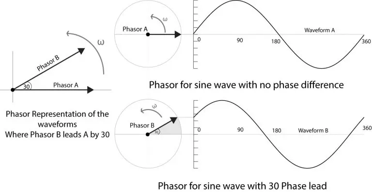
Instead of starting the rotation from zero degrees, a vector may start rotation somewhere else, let’s say 30 degrees. So, what would the waveform look like?
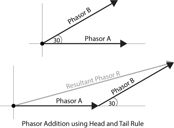
The waveform, in this case, would start from ½ instead of zero, and after completing the positive and negative half-cycles, it will reach ½ to complete a 360-degree rotation. In the following diagram, waveform B leads waveform A by 30 degrees, and the same is represented by the corresponding phasors. Both phasors are plotted over another axis, conveying the same concept of phase relationship.
Where the equations for the waveforms are

Where the phasor equations are

The ejωt is the term that rotates the vectors counter-clockwise with the angular frequency of ω.
Phasor algebra :
Sometimes it is necessary to add, subtract, multiply, and divide alternating waveforms. If there is no phase shift between them, they can be added and subtracted just like scalar numbers. For example, if we have to add two voltages, 50V and 30V with no phase difference, their resultant voltage will be 50+30=80v.
How to deal with phase-shifted alternating waveform phasors?
As there is a phase difference, their direction at any instance is not identical. Taking it into account, the resultant effect can be found using vector operations rather than scalar operations.
- Basic Electrician Test – Check Your Electrical Knowledge
- Complete Guide to Circuit Analysis in Electrical Engineering
Phasor addition:
For example, in a series AC circuit analysis, there is a need for phasor addition of voltages that may have a phase difference. To determine the resultant phasor, the law of parallelogram or the head and tail rule of vector addition is used.
Phasors addition with the parallelogram law:
Let us continue with the above example waveforms, A and B, and their phasors. The phasor A and phasor B form two adjacent sides of a parallelogram, where the diagonal connecting them is the resultant phasor.
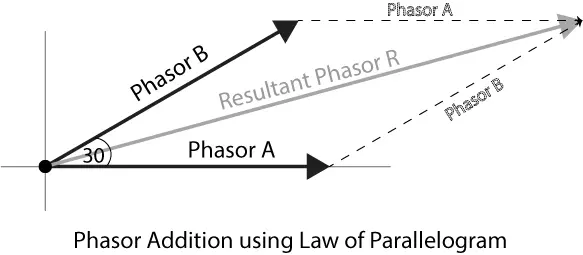
Another way of performing phasor addition is the head and tail rule. In which the tail of a phasor is joined with the head of another phasor. A phasor combining the tail of the first and the head of the second phasor represents the resultant phasor. Both methods have the same output.
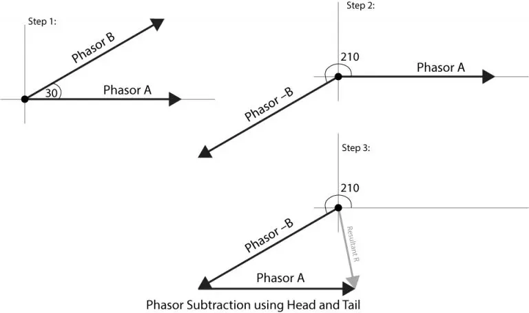
Phasor Subtraction with the head-tail rule:
Phasor addition and phasor subtraction are very similar operations. In the case of subtraction, the direction of the phasor that you want to subtract is reversed. Then the addition is performed to obtain the resultant phasor.
Conversion between Polar and Complex Form:
Complex Form and Phasors:
As phasors are rotating vectors, it is considered that all the phasor of a circuit, like current and voltage phasors, has the same frequency. So, dropping the rotation component ejωt, we only have a vector remaining. Now, this vector can be converted into vertical and horizontal components using the Euler formula. Finding the rectangular components of the phasor B.

Vertical component:

Horizontal component:

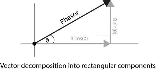
The phasor can also be represented by the combination of these X and Y components as follows

The complex number offers simpler addition and subtraction, while multiplication and division are easy in polar form. Conversion between them takes place through the Euler formula.
- Crane Electrical Systems: Safe, Intelligent, and Efficient Operation
- Electrical Installation Guide: Wiring, Protection & Safety Standards
Complex Form
Phasor Addition:
Suppose two phasors A and B, after dropping the rotational term and converting to the complex form, we want to add them.

The addition process for complex numbers is straightforward; addition is performed between real and imaginary parts separately in phasor algebra. The resultant complex number from the above addition will be

Phasor Subtraction:
For subtraction in phasor algebra, nothing else will change except the sign; the above example will look something like this

Polar Form:
Another way to express a vector in a 2-dimensional plane is the Polar form. The polar form tells the magnitude of the vector and the angle that it makes with the horizontal axis. Taking the above example, the phaser B, after dropping the rotational term, can be written as

The angle is always counted anti-clockwise, starting in the first quadrant of the Cartesian plane.
Phasor Multiplication:
The preferred method for the multiplication of vectors is the polar form because of its simplicity in phasor algebra. The magnitude of the vectors is multiplied where the angle between they are added. Suppose the following two vectors are converted to polar form, where we want to multiply them.

The resultant vector will be

Phasor Division:
The division of a phasor is a reciprocal process of multiplication. In polar form, the magnitude of the vector is divided by the sum of its angles, which are subtracted. Continuing the above example of phasors and their stationary vectors, let me show you mathematically how to perform the division of phasors.
Suppose the above stationary vector in the polar form

We are interested in finding the B/A division of the phasor; the resultant stationary vector will be
