RLC Parallel circuit is a circuit in which all the components are connected in parallel across the alternating current source. In contrast to the RLC series circuit, the voltage drop across each component is common, and that’s why it is treated as a reference for phasor diagrams.
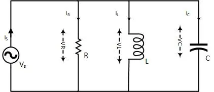
In the circuit diagram, it can be observed that the voltage for the resistor, capacitor, and inductor is the same. Where the resistor current IR, capacitor current IC, and inductor current IL are different. All these individual currents are different from each other as well as from the source current Is. Where the vector summation of these individual currents is equal to the source current.
The impedance of the RLC Parallel Circuit :
The reciprocal of impedance is called Admittance, symbolized by Y, and its unit is Mho, the inverse of Ohm. In contrast to the series RLC circuit, in a parallel RLC circuit, the total impedance formula is as follows.

A convenient way to calculate the same impedance is to use Admittance Y, by the following formula.

As impedance adds up in an RLC series circuit, similarly, admittance adds up in an RLC parallel circuit.
- Crane Electrical Systems: Safe, Intelligent, and Efficient Operation
- Electrical Installation Guide: Wiring, Protection & Safety Standards
Conductance, Susceptance, and Admittance :
Admittance:
The reciprocal of impedance is admittance, represented by Y, and its unit is Mho or Siemens. The physical meaning of the admittance is how easily AC flows in a circuit containing resistance and reactance.
Conductance:
Conductance is the reciprocal of resistance and is represented by the symbol G, and its unit is Mho or Siemens. The physical meaning of conductance is how easily AC flows through a circuit that contains only the resistance component.
Susceptance:
The reciprocal of reactance is called Susceptance B, and its unit is Siemens S. Its physical meaning is how easily current can flow in a reactance-containing circuit.
Susceptance has opposite signs compared to capacitive reactance and inductive reactance. Capacitive Susceptance is positive, and reactive Susceptance is negative.
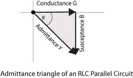
Admittance Triangle in RLC Parallel circuit :
Admittance calculation is comparatively easier for parallel circuits than impedance calculation. The admittance, conductance, and Susceptance can also be drawn over a triangle, which is known as the Admittance triangle.
- Basic Electrician Test – Check Your Electrical Knowledge
- Complete Guide to Circuit Analysis in Electrical Engineering
The admittance triangle is a reflection of the impedance triangle along the horizontal axis. Where resistance is replaced with conductance, reactance with Susceptance, and impedance with admittance.
Applying Phytagourus’ theorem to the admittance triangle, the admittance can be calculated as

Where

From the above equations, the admittance is

Where its corresponding impedance will be

OR

Power Factor in RLC parallel circuit :
The power factor is a ratio that tells how power is utilized for performing the actual work. The PF is represented by the cosine of the phase angle.
The cosine of the angle in the above admittance triangle will give us the following equation.

- Charging EV: A Beginner’s Guide to Electric Vehicle Ownership
- 3D Scanning in Industrial Inspection and Engineering Applications
Example with Solution :
For the following circuit, find the source current IS and each branch’s current IR, IL, and IC, Impedance Z. Also, draw the Admittance triangle and current triangle.
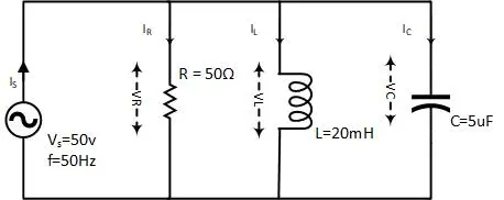
To calculate impedance, we should, first of all, calculate the inductive and capacitive reactance and susceptance.

Where capacitive reactance and Susceptance

Similarly, conductance is

Now impedance and Admittance will be

The admittance triangle can show all these values of conductance, susceptance, and admittance.
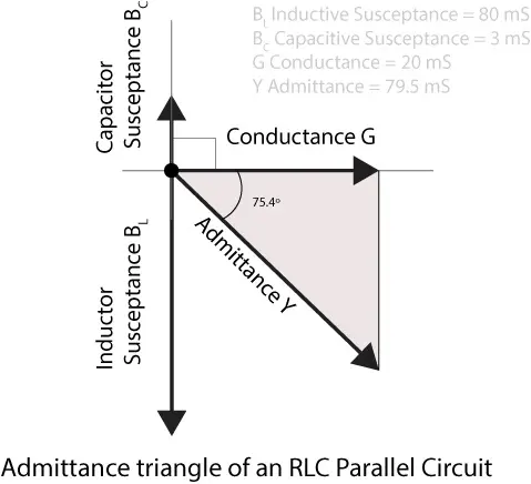
The power factor of the circuit is

Where the angle between current and voltage is

To find the current in each branch, we could use the simple formula

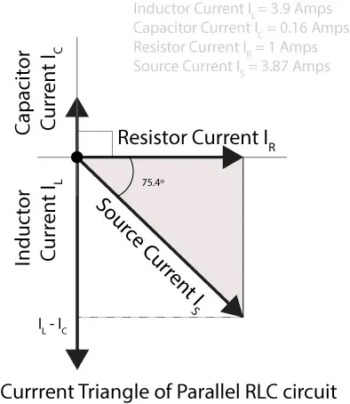
Where the source current is the vector combination of all these individual currents

The same thing is drawn over the vector representation.
Conclusion :
- The resistor, inductor, and capacitor are connected in parallel across an AC source.
- Voltage is common in all components and is taken as a reference for the phasor diagram.
- Impedances of RLC parallel circuit, the addition of admittances.
- The source current is the vector summation of individual currents.