In contrast to the RLC parallel circuit, the RLC series circuit contains all three passive electrical components, Resistor, Capacitor, and Inductor, in series across an AC source. As there is only one path for current in a series combination, the current in all these components is the same in magnitude and phase.
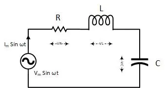
We know that voltage and current are in phase in a pure resistor, while current leads in a purely capacitive circuit, and the case of a purely inductive circuit, current lags. So, what about the voltage across each component, if their behavior is so different?
To answer the question, we will first find the impedance of the series RLC circuit.
Before going further, I would like to take the current phasor as a reference. Because the current is the same in all the components of the RLC series circuit. So, it is more robust to compare different quantities to the same current.
Impedance Triangle in RLC series circuit:
The total impedance of an RLC series circuit can be found using an impedance triangle. First of all, we have to consider the resistance and reactance of each component and then put them into the impedance triangle to find the total impedance of the RLC circuit.
Resistance:

Inductor Reactance:

Capacitor Reactance:

By observing the above equations, the capacitive reactance and inductive reactance are opposite in direction of each other.
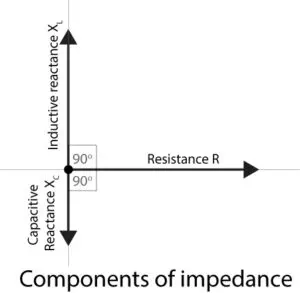
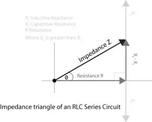
In the impedance triangle, resistance, capacitive reactance, and inductive reactance phasors will be added to each other using the parallelogram law or head and tail rule. The final impedance can be leading or lagging depending upon the difference between the capacitive and inductive reactance magnitude. If the capacitive reactance is larger than the inductive reactance, the impedance phasor will make a negative angle with the horizontal line or vice versa.
In the above impedance triangle, I have assumed inductive reactance is larger, and it is making a positive angle with the resistance phasor. The total impedance of the RLC circuit is represented by the following formula

Current in the RLC series circuit:
According to Ohm’s Law in an AC circuit, the current of an AC circuit can be found using the following formula
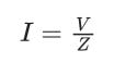
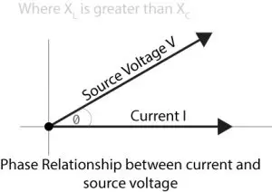
The phase difference between the current and voltage will depend on the impedance. If the impedance is more inductive, the current will lag, and if the impedance is more capacitive, then the current will lead.
- Crane Electrical Systems: Safe, Intelligent, and Efficient Operation
- Electrical Installation Guide: Wiring, Protection & Safety Standards
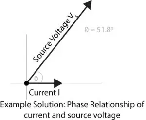
As I have assumed inductive reactance larger than capacitive, so the current, in this case, will lag behind the source voltage.
The voltage across each component in the RLC series circuit :
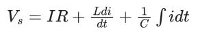
Applying KVL to the RLC circuit, we will get the following equation

Using the basic current and voltage relationship in resistor, inductor, and capacitor current flow, the above equation can be modified as follows.
The voltage across each circuit element can be found using the following formula.
Resistor voltage drop:

Inductor voltage drop:

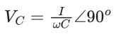
Capacitor voltage drop:
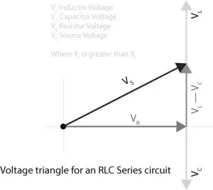
The voltage drop in the resistor will be in phase with the current; in the case of the capacitor, the current will lead to a voltage drop, and for the inductor, the current of the inductor will lag behind the voltage drop in the inductor. The same thing is represented with the phasor diagram.
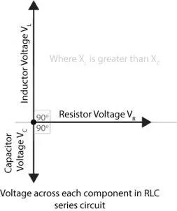
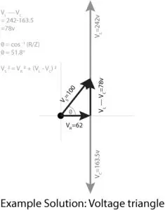
The above vectors from the above diagram can be added vectorially, which will get us to the voltage triangle. The vertical component of the triangle shows the voltage drop across reactance (inductive and capacitive), and the horizontal component shows a drop across the resistance.
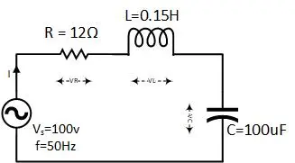
Example with the solution:
For the given circuit diagram, calculate the RLC series circuit impedance, current, voltage across each component, and power factor. Also, draw the phasor diagram of current and voltage, impedance triangle, and voltage triangle.
- Charging EV: A Beginner’s Guide to Electric Vehicle Ownership
- 3D Scanning in Industrial Inspection and Engineering Applications
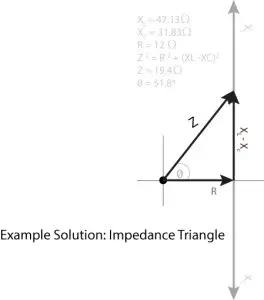
First of all, let me calculate the total impedance with the following formula
Resistance:

Inductive Reactance:

Capacitive Reactance:

Now the total impedance will be

Where the current is

The voltage across each component in the RLC circuit
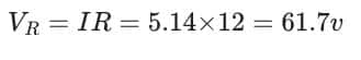
The voltage across the resistor:
Voltage across the capacitor:

The voltage across the inductor:

- Basic Electrician Test – Check Your Electrical Knowledge
- Complete Guide to Circuit Analysis in Electrical Engineering
Observing the above individual voltages, their scalar summation can get us a larger voltage than the source voltage. Take a look at the following vector diagram.
Where the power factor of the circuit is

From the above calculation, we have observed that inductive reactance is larger than capacitive, so the power factor is considered lagging.

RLC Series circuit calculator :
RLC circuit calculator calculates the inductive impedance, capacitive impedance, total impedance, and total current. It also calculates the voltage across the resistor, inductor, and capacitor, and the phase angle between the current and voltage.
Conclusion:
- If the resistor, inductor, and capacitor are connected in a series AC circuit, the circuit will be called an RLC series circuit.
- The phase difference between voltage and current is adjusted by the difference between capacitive and inductive reactance.
- In the impedance and voltage triangle, quantities are added vectorially.
- If inductive reactance is larger, the circuit will respond as if it is an inductive circuit, and vice versa.