Electrical components can be connected in two ways: either a Series connection or a Parallel connection. Both types of connections have their advantages and uses. We will start by looking at the series connection. Use the resistor in the series calculator to accelerate your calculation.
Series Resistor connection:
Two components will be called in series if the node where they are connected has no other components connected to it.
- Charging EV: A Beginner’s Guide to Electric Vehicle Ownership
- 3D Scanning in Industrial Inspection and Engineering Applications
Suppose two resistors are connected at point b, and the head of the second resistor is connected to the tail of the first resistor. Resistors commonly have no heads and tails. But when current flows, you may assign them heads and tails by assigning positive and negative signs based on the voltage drop, as shown.
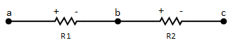
The Series circuit provides only one path for the current.
Notice that there is only one path for the current to flow. The positive terminal of R2 is connected to the negative terminal of R1, and there is no circuit element connected to that point based on the supposition that current is flowing from point A toward point C. If there is any third circuit component (source or resistor) connected to point b, the R1 and R2 will no longer be in series with each other.
The Resistor in the Series Calculator:
The Resistor in the Series Circuit Formula:
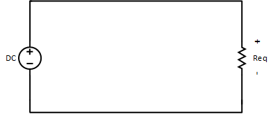
Up till now, we have defined and tried to identify the type of circuit. The next step is to learn how to find equivalent resistance in a complex circuit. Suppose we have the following complex circuit, and we are interested in answering the following questions.
What is the total current, the source is providing?
To find out the total current source provided, first, we need to know how much resistance the source experiences. The total resistance we can calculate using the following formula, or use the resistor in the series calculator. Here “n” is the total number of resistors connected in series, in our case n=3.

Suppose R1, R2, and R3 are 20, 40, and 10 Ω, respectively. By putting the values in the above formula, we get:

After finding the equivalent resistance, the circuit can be reduced to the following circuit, and the total current.
- Basic Electrician Test – Check Your Electrical Knowledge
- Complete Guide to Circuit Analysis in Electrical Engineering

What is the current in each resistor?
For all the resistors in a series circuit, there is always only one path for the current to flow. Because of being on the same path, the current is always the same for all series-connected resistors, as the following equation represents.

Here I1, I2, and In are the currents of R1, R2, and Rn, respectively, and n represents the total number of resistors. In our case, the currents for R1, R2, and R3 are I1, and I2 and I3 are 2 amperes.
IT = 2 A
I1 = 2 A,
I2 = 2 A,
I3 = 2 A
What is the voltage across a series resistor?
It is effortless, and Ohm’s law is the best tool for it because we have the resistance and current of each resistor, so we can find the corresponding voltage easily.
V1 = I1 R1 = 2 A x 20Ω = 40 volts
V2 = I2 R2 = 2 A x 40Ω = 80 volts
V3 = I3 R3 = 2 A x 10Ω = 20 volts

Note that the total voltage drop across the circuit is exactly equal to the voltage applied to the circuit. It also satisfies Kirchhoff’s Voltage Law (KVL). The expression for voltage can be generalized like this.

The voltage drop in the series connection can easily be calculated by using the Voltage Divider Rule.