
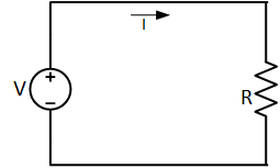
Ohm’s law states that the current flowing in a resistor is directly proportional to the voltage across the resistor. It can be mathematically expressed as

Where I is the current in the resistor, V is the voltage across the resistor, and R is the resistance of the resistor.
Ohm’s law is one of the basic electrical engineering laws. It provides a relationship between voltage V and current I, such that current depends on voltage.
Ohm’s law is one of the basic electrical engineering laws. It provides a relationship between voltage V and current I, such that current depends on voltage.

Ohm’s Law Formula:
The above statement means that if we gradually increase the voltage across a conductor, the current flow will also change with a constant ratio, as the graph shows below.

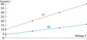
The above graph and statement can be represented mathematically as follows:
Converting the proportionality into an equation leads to a constant “R”, known as Resistance.
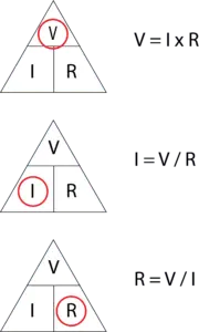
Ohm’s Law Chart
The voltage, current, and resistance formulas can be easily obtained from the following chart based on the parameters given and required.
The relationship can be rearranged to determine any element if the other two are given, as the Ohm’s law triangle represents.
Ohm’s Law Calculator:
Enter any two parameters to calculate the third one in the Ohm’s Law calculator.
Fluid Analogy:
Let us consider a tank filled with water at a certain height with an opening at the bottom. If the water level is higher inside the tank, more water will flow out of the tank. Or, if the water level inside the tank is low, less water will flow out of the tank. Similarly, Ohm’s law relates voltage (water level) and current (water flow) to behave in the same way.

Current, Voltage, and Resistance Relationship:
The current and voltage are directly related to each other. As you increase one of them, the second will also increase to maintain a constant resistance of the circuit. Where resistance has an inverse relation with current and a direct relation with voltage.
- Charging EV: A Beginner’s Guide to Electric Vehicle Ownership
- 3D Scanning in Industrial Inspection and Engineering Applications
Resistance and Conductance:
The term Resistance can be defined as: “The amount of opposition provided by a conductor or any other component in the path of current flow is known as resistance.” If we use units of current and voltage in amperes and volts, respectively, then the unit of resistance is called an ohm (named after a scientist), which is equal to a volt per ampere and represented by Ω.
The inverse of resistance is conductance, which shows the ease of electric current passage. It is represented by “G”, and its unit is mho (inverse of an ohm), represented by ℧. Nowadays, its unit is represented by Siemens S.
Resistivity and conductivity:
Resistance is dependent on the material used for conduction and varies from material to material. Some materials may conduct more current than others for the same amount of voltage. The property of materials to oppose electric current is known as resistivity, also known as specific resistance.
- Charging EV: A Beginner’s Guide to Electric Vehicle Ownership
- 3D Scanning in Industrial Inspection and Engineering Applications
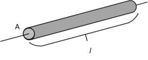
The resistance of a wire depends on some factors, such as its length, cross-sectional area, and the material used in the wire. Resistance is directly proportional to the length of the wire and indirectly proportional to the square of the cross-sectional area, as shown in the diagram.

Ohm’s Law in AC:
Ohm’s law is not directly applicable to AC circuits, which involve inductors, capacitors, and/or transmission lines. The law can only be useful for pure resistive AC circuits without any alterations. In the RLC AC circuit, the total opposition to the current is impedance Z, which is the combination of two orthogonal elements, resistance and reactance.

C represents the total capacitance of the circuit, L represents the total inductance of the electrical circuit, and f represents the frequency of the AC source.
Ohmic and Non-Ohmic Components:
Ohmic components are those that obey Ohm’s law for all values of voltage, current, negative and positive. Precisely saying, the value of R=V/I remains unchanged over long-range, i.e, Resistors.
Whereas in non-Ohmic components, where R=V/I varies the value of voltages and/or currents, i.e., diodes.
- Basic Electrician Test – Check Your Electrical Knowledge
- Complete Guide to Circuit Analysis in Electrical Engineering
Conclusion:
Ohm’s law is a very basic and important tool in electrical engineering. The above discussion clarifies that current is directly proportional to voltage. Multiple resistors can be combined to get a specific current.
FAQs
What does Ohm’s law state?
Ohm’s Law states that the current (I) flowing through a conductor is directly proportional to the voltage (V) across it, with the proportionality constant being the resistance (R). Mathematically, it is expressed as I = V/R.
Do light bulbs follow Ohm’s law?
Generally, light bulbs do not strictly follow Ohm’s Law. As the temperature of the filament changes with the current, the resistance can vary, causing deviations from a linear relationship between voltage and current.
How does vasoconstriction affect the factor(s) in Ohm’s law?
Vasoconstriction, the narrowing of blood vessels, increases resistance (R) in Ohm’s Law. As vessels constrict, the resistance to blood flow rises, affecting the relationship I (current) = V (voltage)/R.
When was Ohm’s law discovered?
Ohm’s Law was formulated by German physicist Georg Simon Ohm in 1827.
Is there a demonstration fluid analogy to Ohm’s law?
In a fluid analogy for Ohm’s Law, water flow represents electrical current, pressure difference is voltage, and obstacles in the pipe symbolize resistance.
I REALLY APPRECIATE THE NOTES ARE VERY GOOD
excellent.