Nodal analysis is a circuit analysis technique and is based on Kirchhoff’s Current Law (KCL) with coordination of Ohm’s law. The analysis uses node voltage instead of element voltage in the circuit; that’s why it is called Nodal Analysis.
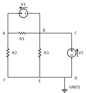
Where nodes are the junction part of the electric circuit that connect multiple components. Points “A” and “B” are nodes in the following circuit.
Nodal Analysis Steps:
- Select a node as a reference.
- Assign voltage names, i.e., v1, v2, and v3, to the remaining nodes, concerning the reference node.
- Apply KCL to each non-reference node and write equations.
- Use Ohm’s law to express the current in each branch.
- Now solve the resulting simultaneous equations with any kind of tool or technique to get node voltages.
Example:
Suppose we have to analyze the circuit given below, using nodal analysis. We know the following parameters of the circuits given below.
The resistors:
R1= 4Ω
R2= 2Ω
R3= 6Ω
The current sources:
Ix= 5A
Iy= 10A
- Charging EV: A Beginner’s Guide to Electric Vehicle Ownership
- 3D Scanning in Industrial Inspection and Engineering Applications
Solution:
Select Reference Node:
We would be selecting a reference node. I select the “Vo” node as my reference node. The reason for that is that the ground terminal is attached to that node. And we know that the voltage at the ground point is considered zero. So, the selection will ultimately simplify our later calculations, and it is also advisable for you to ground as your reference point if there is any.
Assign a Name to Each Node:
There is a total of three nodes in the circuit, so now, I will be assigning a name to the rest of the nodes, according to the second step. See the diagram below. I named the node as follows. But keep in mind that the voltages at these nodes are defined with respect to the reference node.
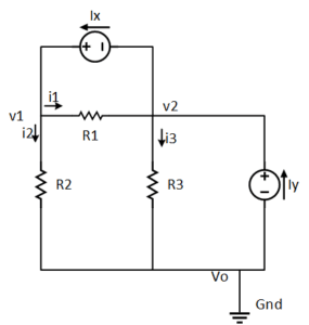
Apply KCL at each node:
Now, apply KCL at each non-reference node and write equations.
KCL at node named v1: Ix = i1 + i2
KCL at node named v2: Iy = i3 – i1
Where we know the values of Ix and Iy are 5A and 10A, by putting the values, the equations become:
5 = i1 + i2 — (1)
10 = i3 – i1 —(2)
Apply Ohm’s Law:
Now apply Ohm’s law to express each current. Since resistance is a passive component, by the passive sign convention, the current always flows from higher potential to lower potential.
We start from the current i1:

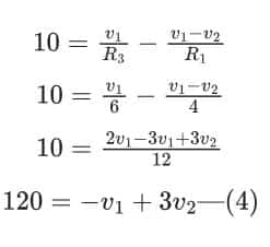
Now, substituting these values of currents in the above equations (1) and (2) will give us two equations in variables v1 and v2.
From equation (1):

From equation (1):
Solve the system of equations:
We got two simultaneous equations, i.e., (3) and (4), with two unknown variables. So we can find it easily. Let’s do it by converting it to a matrix, as given below:

Row2 is replaced with 3Row1+Row2:

Now, we can extract the value of v1 from the second row, as below:

Putting the value of v1 into the first-row equation, like this:

Now we know the voltages of all the nodes, and we have equations for all branch currents, so we can easily analyze the circuit element by element. I am considering a special case of i1 here for further understanding. Suppose we want to know the current i1, we can do it like this:

The answer here for i1 is negative, which means that the current i1 is not flowing in the direction we considered. But it does NOT mean that it is wrong. So, pick any random direction as I picked here, and solve your problem. At the end, you will know the exact directions of each current.
- Basic Electrician Test – Check Your Electrical Knowledge
- Complete Guide to Circuit Analysis in Electrical Engineering
Nodal Analysis with Voltage Sources:
The above example calculation was all about nodal analysis when there are current sources. When it comes to a voltage source in the nodal analysis, you have to apply KCL as well as KVL to the circuit to get the equation.
There are two cases when solving voltage sources in the nodal analysis.
Case 1:
When a voltage source is between a reference node and a non-reference node, as shown below (just like v1 and ground). The non-reference node becomes known by being connected to the voltage source. It makes the calculation simpler. In the circuit below, you don’t have to find the voltage at the node named v1 cause the voltage at the node is already known.
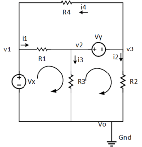
Case 2:
When the voltage source is connected between two non-reference nodes, as shown in the above diagram (just like v2 and v3). Both nodes are considered as a single node named a super-node. First of all, write the KCL equation for the super-node, just like this:

Now apply Ohm’s law to each current, which will give you a variable in terms of node voltages. After that, apply KVL at the loop v2, v3, and vo will give us:

Where Vx is a known parameter of the circuit.