Norton’s theorem says that a linear two-terminal electric circuit may be replaced with a Norton equivalent circuit. Norton Thoerm circuit consisting of a current source, IN, in parallel with a Norton resistor RN. Where IN is the short-circuit current through the terminal load resistor, and RN is the equivalent resistance at the terminals when all the independent sources are turned off. In this post, we will learn how to use the Norton theorem with examples.
Just like the Thevenin Theorem, Norton Theorem is also useful to analyze a single resistor that changes frequently and the rest of the circuit remains the same. In contrast to the Thevenin Theorem, the Norton Theorem reduces it to a single current source instead of a voltage source. An American Engineer, E. L. Norton, 1926, proposed that a circuit can be reduced to a single current source, two resistors, RN, parallel with the current source, and the load resistor, RL, frequently changing a resistor.
- Charging EV: A Beginner’s Guide to Electric Vehicle Ownership
- 3D Scanning in Industrial Inspection and Engineering Applications
Norton Resistor RN is the same as Thevenin’s resistor Rth, and Norton Current IN is Vth/RN. So, this implies that the Norton Theorem is not more than the source transformation of the Thevenin Theorem.
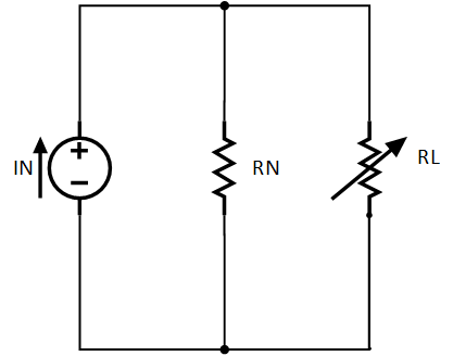
Norton Equivalent Circuit
According to the Norton theorem, any linear circuit can be reduced to a single current source in parallel with RN, which is calculated from the load resistor end, keeping all dependent sources.
The current of the current source can be calculated from the load resistor terminal voltage, keeping it open. The generic Norton Equivalent circuit is shown in the diagram below.
Norton Theorem Examples
Suppose we want to connect a variable resistor at terminal A-B and find Norton’s equivalent circuit for the following example for the terminals.
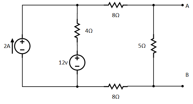
Solution: How to Use Norton’s Theorem
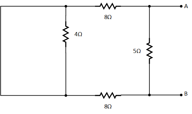
Find Norton Equivalent Resistance
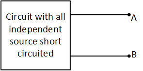
First of all, we have to replace all independent voltage sources with closed and current sources with an open circuit, as shown in the figure below.
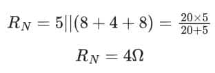
Now we will find equivalent resistance from the terminal A and B points of view, as shown by the direction of the arrow in the diagram above. So, Norton resistor RN will be:
Find Norton Voltage:
To find IN, first, we find out the voltage at terminal A-B while it is open-circuited. So the circuit becomes something like this:
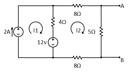
You can use any method you want. Here I am using mesh analysis and writing equations as below:
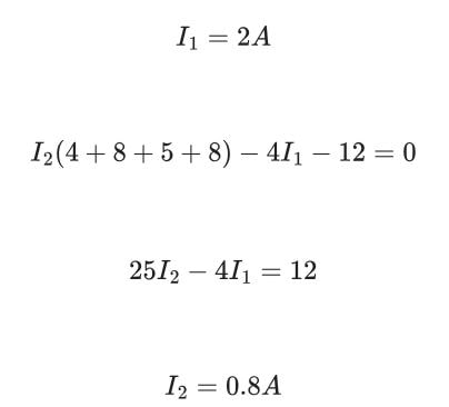
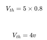
The current I2 is flowing through 5Ω, so the voltage across the resistor will be:
- Charging EV: A Beginner’s Guide to Electric Vehicle Ownership
- 3D Scanning in Industrial Inspection and Engineering Applications
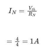
Find Norton Current
Now we have both resistance RN and voltage Vth, so we can find out the Norton current IN as follows:
The Norton equivalent circuit for terminals A and B will be as follows:
At terminals A-B we can put any resistor we need. We can analyze the resistor current through the current divider rule instead of going into complex circuit calculations.
What type of circuits do Thevenin and Norton’s theorems apply to?
Thevenin and Norton’s theorems apply only to linear circuits. The linear circuit is where the circuit parameters, i.e., resistance, current, voltage, frequency, and gain, don’t change with a change in current or voltage.
What is the purpose of Thevenin’s and Norton’s theorems?
The purpose of Thevenin’s and Norton’s Theorems is to simplify the circuit. If the load frequently changes during the circuit analysis, the circuit is simplified with Thevenin’s or Norton’s theorem.
Find Norton Voltage:
To find IN, first we find out the voltage at terminal A-B, while it is open circuited. So the circuit becomes something like this:
Norton Theorem
You can use any method you want, here I am using mesh analysis and writing equations as below:
I1=3A is wrong. it is 2A, please correct it.
Thanks Dita. The corrections are made.