According to the Thevenin Theorem, a complex linear electrical circuit containing several electrical resistances, voltage, and current sources can be simplified. The simplified circuit with a fixed resistor called the Thevenin equivalent resistance Rth, in series with a variable load resistor, which varies frequently, RL, and a Thevenin voltage, Vth. In other words, any one-port electrical network can be reduced to a single voltage source and a single resistor circuit. The Theorem holds for any black box linear circuit, regardless of how complex the circuit is.
According to the circuit laws, when a single resistor changes, the whole set of parameters (voltage and current) changes. When a circuit has a variable resistor, it becomes frustrating to calculate over and over. Practically, it happens more often. Consider your home outlet where you plug in a fan, iron, and phone charger according to your requirements. In 1883, M. Leon Thevenin provided a handy technique to avoid this problem and save time.
- Charging EV: A Beginner’s Guide to Electric Vehicle Ownership
- 3D Scanning in Industrial Inspection and Engineering Applications
The Thevenin Theorem also holds for AC circuits, where the circuit may contain reactive and resistive impedance loads.
Norton’s Theorem can also reduce a complex circuit to a three-element circuit. But Norton’s Theorem replaces the source with a current source and a Norton Resistor in parallel with the load resistor.
Thevenin Resistance Rth and Voltage Vth :
Thevenin’s theorem is a very handy tool for simplifying the analysis of large electrical circuits. A complex original circuit may be replaced by an independent voltage source and two resistors; the first load resistor, which changes frequently, and the Thevenin Resistance, the remaining circuit resistance, both in series. A voltage source, Vth, is the voltage across the load resistor when the circuit is open, which is called the Thevenin Voltage. So, the technique is quite easy, just find the Thevenin resistor and voltage, and you are done. I will explain the theorem with the following example.
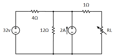
Example: For the circuit below with a load, what is the Thevenin equivalent resistance?
Suppose we have the following circuit, with a load resistor that changes frequently, which is why it’s shown as a variable resistor.
Solution :
Find Thevenin Resistance:
To find the Resistance, remove the load resistor, short the independent voltage source, and open the current sources. The circuit will look like this:
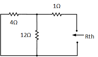
Now we have to find the Resistance, Rth, from the right-hand side (as the arrow points in the diagram).

- Basic Electrician Test – Check Your Electrical Knowledge
- Complete Guide to Circuit Analysis in Electrical Engineering
Find Thevenin Voltage:
Now, to find the Voltage, Vth, we remove the load resistance RL and find the voltage at that terminal.
First, make changes to the circuit and redraw it as follows:
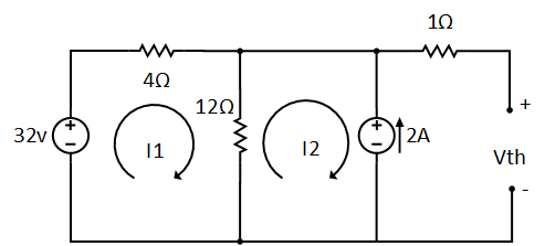
Now in the circuit above, we have to find the Vth, the Thevenin voltage, using any technique we want. Here, I am applying mesh analysis to the circuit, which gives me the following equation:

Solving for I1, we get I1 = 0.5A and Vth:

Notice that I have ignored the 1Ω resistor in finding Vth because no current will flow through it.
So far, we have calculated the Thevenin Resistance and Voltage, and we will now plug them into the following circuit. To calculate the current, the supply voltage is divided by the equivalent resistance, keeping Ohm’s law in mind.
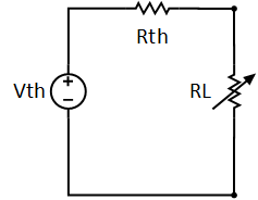
Using the Voltage Divider Rule, the formula for current IL is:

Suppose if RL= 6Ω, the current IL will be:

Suppose if RL= 16Ω, the current IL will be:

Suppose if RL= 36Ω, the current IL will be:

The Theorem with dependent sources :
It is quite easy to solve a circuit using the Thevenin theorem when it has only an independent source in it. The fact that the output of the dependent source varies with circuit parameters means that they are treated differently. To find Resistance and Voltage (Rth and Vth) in the case of dependent sources, we use two approaches as explained below.
- We apply a voltage source, Vo, at the terminals of the load resistor, RL, and determine the resulting current, Io. Then Rth = Vo / Io.
- Alternatively, we may insert a current source, Io, at the terminal load resistor, RL, and find the terminal voltage, Vo, then Rth = Vo / Io.
Either the approach assumes some voltage or current at the terminal of the load resistor, RL, and will lead to the same results. It often occurs that Rth takes negative values, which implies that the circuit is supplying power.
Conclusion:
- A complex circuit can be converted into a single voltage source circuit by using the theorem.
- Thevenin’s theorem is used where a single resistor is considered, which varies frequently.
- Thevenin resistor and voltage source should be connected in series with the load resistor.
- All the voltage sources are short-circuited, while all the current sources are open-circuited to find the Resistance Rth.
- The original circuit is replaced with Rth, Vth, and the load resistor
- The technique uses a linear electrical circuit with several voltage and current sources.
How do you get a Thevenin equivalent circuit inductor?
First, identify the portion of the circuit where the inductor is located to get the Thevenin equivalent circuit of an inductor. Then, remove the inductor and calculate the open-circuit voltage and equivalent resistance seen from its terminals. Replace the circuit with a voltage source (Thevenin voltage) in series with the equivalent resistance to form the Thevenin equivalent.