Skip to content

Electric Shocks | Electrical Engineering Tutorials

Practical Electrical Guide and Industrial Solutions

  • Home
  • Blog
    • Electrical Engineering
    • Electronics Engineering
    • Electrical Installation
    • Solar Energy
    • MCQs
    • Books
  • Graph Plotter
  • Calculators
  • Services
    • Forum
    • Other Services

RLC Parallel Circuit Analysis and Online Calculator
October 30, 2026October 3, 2018 by Gul Faraz
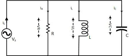
RLC Parallel example circuit diagram

In RLC parallel circuit, resistor, inductor, and capacitors are connected in parallel across Alternating current source. In contrast to the RLC series circuit, the voltage across each component is the same and is taken as reference in the phasor diagram.
Categories Circuit Analysis

RLC Series circuit, Phasor Diagram and Online Calculator

October 30, 2026September 27, 2018 by Gul Faraz
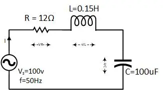
RLC Series Circuit Example with solution

RLC Series circuit contains a resistor, capacitor, and inductor in series combination across an alternating current source. The behavior of components can be explained by phasor diagrams, impedance and voltage triangles.

Categories Circuit Analysis Tags Alternating current, capacitor, Electrical Engineering Calculators, Electrical Inductor, Resistors

Power Electronics Handbook by Muhammad H. Rashid

February 25, 2026September 18, 2018 by
Power Electronic Handbook by Muhammad H. Rashid 4th Edition

This handbook is a textbook for power electronics Starting from the electronics devices like Diodes, Transistors, SCR and so on. Then Muhammad H. Rashid explains its applications like DC-DC, DC-AC, AC-DC, AC-AC converter.

Categories Engineering Book & PDFs Tags Electronic Devices, Power Electronics

Phasor Algebra in AC circuit Analysis: Addition and Multiplication

February 23, 2026September 13, 2018 by
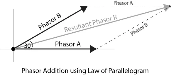
Parallelogram law for vector / phasor addition

Phasor diagram in an AC circuit analysis is to represent the phase angle i.e. leading and lagging effect through vector representation. Phasor algebra, polar form, and complex number conversions are also explained.

Categories Circuit Analysis Tags Alternating current

The First course on Power Electronics and Drives

February 25, 2026September 6, 2018 by
The first course on power electronics and drive by Ned Mohan and Mnpere

The author Ned Mohan tried his best to prepare students for industries by providing a broad and depth knowledge of power electronics by giving the gift of “The first course on Power Electronics and Drive”.

Categories Engineering Book & PDFs Tags Electronic Devices

Power Factor in an AC circuit Explained with Power Triangle

August 8, 2025September 2, 2018 by
https://electric-shocks.com/wp-content/uploads/2018/09/Average-Power-in-AC-circuit-and-the-role-of-power-factor.jpg

Power Factor (PF) play an important role in average power dissipation in an ac circuit. PF leads to the concept of three different real, reactive and apparent power, which is better explained by Power triangle.

Categories Circuit Analysis Tags Alternating current, capacitor, Electrical Inductor, Resistors 1 Comment

How to Calculate Impedance Triangle: Resistance and Impedance

August 8, 2025August 28, 2018 by
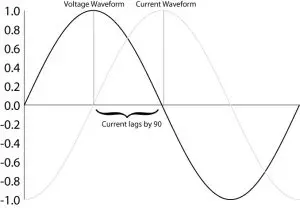
current is leading in inductor

Capacitor and inductor oppose current in AC circuit because of inertia of electron motion, which is called capacitive and inductive reactance respectfully.

Categories Circuit Analysis Tags Alternating current, capacitor, Electrical Inductor, Resistors

Difference between Alternating Current and Direct Current

August 8, 2025August 25, 2018 by
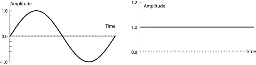
Difference between Alternating Current and Direct Current

Alternating current (AC) is the type of electrical current which changes its direction and magnitude every moment.

Categories Circuit Analysis Tags Current Source, Voltage Source

Inductor Charging and Discharging in RL Circuit Analysis Equations

February 18, 2026August 20, 2018 by
LR circuit analysis

In RL series circuit, during the inductor charging phase, the voltage across the inductor gradually decrease to zero and the current through the inductor goes to the maximum in five-times constant (5 taus).

Categories Circuit Analysis Tags Electrical Inductor 6 Comments

PSpice for circuit theory and electronic devices by Paul Tobin

October 31, 2026August 17, 2018 by Gul Faraz
Circuit theory and Electronic devices

PSpice for Circuit Theory and Electronic Devices is one of a series of five PSpice books and introduces the latest Cadence Orcad PSpice version 10.5 by simulating a range of DC and AC exercises.

Categories Engineering Book & PDFs Tags Theorem
Older posts
Newer posts
← Previous Page1 … Page20 Page21 Page22 … Page24 Next →

What are you looking for?

You may like to know

  • Center Tapped Full Wave Rectifier: Circuit, Working, Filter
  • Solar Inverter Firmware Update: Complete Guide for Top Brands
  • How to Add Solar Panels to an Existing System (Cost & Guide)
  • TV Aerial Guide: In which direction do I point my TV Aerial?
  • Best 100 Watt Inverter for Your Application
  • How to Read Solar Inverter Display: Complete Guide to Every Reading
  • How to Test SCR with a Multimeter (Digital & Analog Step-by-Step)
  • What Is SCR? Construction, Working, and VI Characteristics
  • How to Properly Turn Off an SCR Once It Is Conducting
  • How to Calculate Resistor Color Code (4-Band & 5-Band Chart)
© 2026 Electric Shocks | Electrical Engineering Tutorials • Built with GeneratePress