Skip to content

Electric Shocks | Electrical Engineering Tutorials

Practical Electrical Guide and Industrial Solutions

  • Home
  • Blog
    • Electrical Engineering
    • Electronics Engineering
    • Electrical Installation
    • Solar Energy
    • MCQs
    • Books
  • Graph Plotter
  • Calculators
  • Services
    • Forum
    • Other Services

Zener Voltage Pass Regulator Explained with Example
October 31, 2026November 1, 2019 by Gul Faraz
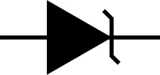
Zener Diode Symbol

A Zener Diode is a special purpose diode used for voltage regulation in reverse bias. Zener diode work under breakdown region for typical operation. A minimum current of Zener knee current must be maintained to keep the voltage regulated.

Categories Electronics Engineering Tags diode, Voltage Source

Derivation of Diode Current Equation, Calculator, and Example

October 14, 2026September 4, 2019 by Gul Faraz
Symbol of diode

The diode current equation depends on the dark saturation current, the charge of an electron, and external voltage. We also provide a calculator for the diode current equation.

Categories Circuit Analysis Tags Current Source, diode, Electrical Engineering Calculators

3 Methods of testing a diode with multimeter and oscilloscope

March 2, 2026August 15, 2019 by Gul Faraz
Testing a diode

Testing a diode with a digital multimeter in two ways, diode testing portion, and ohmmeter. A diode test is considered passed if it shows low resistance/voltage drop on forward bias and high resistance/voltage drop in reverse bias. A diode curve tracer uses an oscilloscope for VI characteristics graph.

Categories Circuit Analysis Tags Current Source, diode, meter, Voltage Source

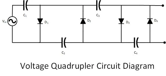
Diode Voltage Doubler Circuit with Tripler and Quadrupler

February 18, 2026August 9, 2019 by Gul Faraz
voltage quadrupler

Voltage Multipliers are electric circuits to increase the voltage by a factor of two, three or four in case of Voltage Doubler, Tripler or Quarple respectively. The Voltage multiplier circuit uses capacitors and resistors to enhance the voltage level.

Categories Circuit Analysis Tags Alternating current, capacitor, diode, Voltage Source 1 Comment

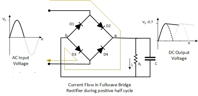
Circuit Diagram for Fullwave Bridge Rectifier with Capacitor

November 13, 2026June 3, 2019 by Gul Faraz
fullwave bridge rectifier current flow during positive half cycle

The Bridge type full wave rectifier can convert an AC to DC by the mean of four diodes in such configuration that the output peak voltage remains equal to secondary of transformer peak. In each half cycle, a set of two diodes conduct and block the current alternately.

Categories Electronics Engineering Tags Alternating current, diode 10 Comments

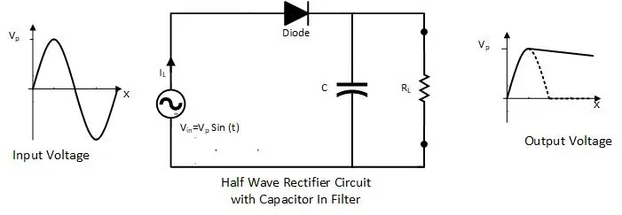
Half wave Rectifier with a Capacitor Filter Design

February 25, 2026January 20, 2019 by
Half wave rectifier Circuit with Capacitor in filter

Rectifiers are the circuit which converts AC Voltage to DC voltage. The half wave rectifier is the simplest type of rectifier with a single diode. The output of the rectifier is filtered with a capacitor filter to smoothen.

Categories Electronics Engineering Tags capacitor, diode 5 Comments

Forward Bias and Reverse Bias of a Diode: Diagram and Graph

November 13, 2026December 25, 2018 by
forward bias and Reverse bias of diode

A diode can be connected in forward and reverse bias with a source. In Forward bias connection, a diode conducts current like a closed switch. Where in reverse bias, a diode blocks current like an open switch.

Categories Electronics Engineering Tags diode, Electronic Devices, Power Electronics, Voltage Source 4 Comments

Depletion Region formation in PN Junction diode

August 7, 2025December 9, 2018 by
PN Junction Diode

At the time of developing the PN junction diode, the depletion region is formed. Where free electrons and hole cross the conjunction between P- and N-region and recombine.

Categories Electronics Engineering Tags diode

Differentiate Intrinsic & Extrinsic Semiconductors: P-Type & N-Type

February 25, 2026November 17, 2018 by Gul Faraz

A semiconductor is a type of electrical material, which is used in electronic devices like PN junction diode, transistor and many more a replacement for a vacuum tube. The semiconductor can be intrinsic or extrinsic, where extrinsic has N-type and P-type.

Categories Electronics Engineering Tags Electronic Devices, Fundamental of electrical engineering, Power Electronics 1 Comment

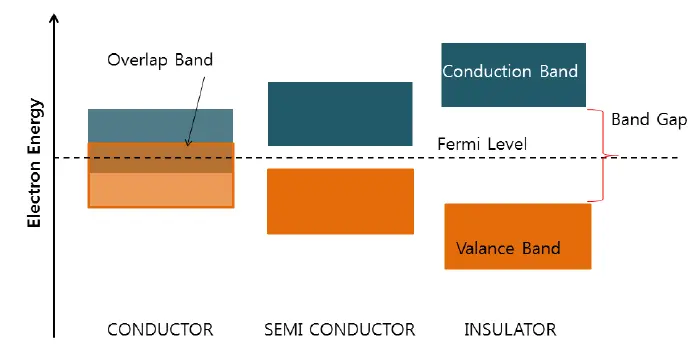
Differentiate Electrical Conductor, Semiconductor and Insulator

February 25, 2026October 11, 2018 by Gul Faraz
Conductance Shell and Valance Shell

Based on electrical resistivity, a material can be divided into three types: conductor, insulator, and semiconductor.

Categories Electronics Engineering Tags Electronic Devices, Resistors
Older posts
Newer posts
← Previous Page1 … Page19 Page20 Page21 … Page24 Next →

What are you looking for?

You may like to know

  • Center Tapped Full Wave Rectifier: Circuit, Working, Filter
  • Solar Inverter Firmware Update: Complete Guide for Top Brands
  • How to Add Solar Panels to an Existing System (Cost & Guide)
  • TV Aerial Guide: In which direction do I point my TV Aerial?
  • Best 100 Watt Inverter for Your Application
  • How to Read Solar Inverter Display: Complete Guide to Every Reading
  • How to Test SCR with a Multimeter (Digital & Analog Step-by-Step)
  • What Is SCR? Construction, Working, and VI Characteristics
  • How to Properly Turn Off an SCR Once It Is Conducting
  • How to Calculate Resistor Color Code (4-Band & 5-Band Chart)
© 2026 Electric Shocks | Electrical Engineering Tutorials • Built with GeneratePress