In the previous article, we saw the Half-wave rectifier’s working principles. The Half-wave rectifier converts only the positive half cycle of AC voltages into a DC voltage and ignores the negative half cycle. That is why its average output is around 32% of the peak voltage. A full-wave rectifier converts the complete cycle into DC with a higher average output. There are two types of Full-wave rectifiers: the center-tapped rectifier and the Bridge Rectifier. We are discussing the Center-Tapped Full-wave Rectifier here.
Full-wave Center Tapped Rectifier operation:
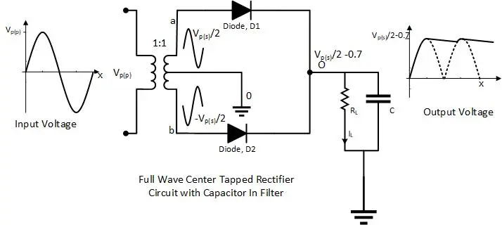
The fact that a Center-Tapped Rectifier uses a center-tapped transformer in its circuit is why it is named a Center-Tapped Rectifier. The secondary winding of the center-tapped transformer is divided in half. As the circuit below shows, the center tap of the secondary winding is grounded, and each diode is connected to the remaining terminals of the secondary winding. The load is connected to the common point of both diodes, and the other side is grounded.
- Basic Electrician Test – Check Your Electrical Knowledge
- Complete Guide to Circuit Analysis in Electrical Engineering
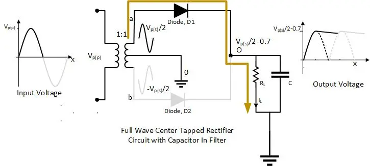
Positive Half cycle:
For the positive half cycle, the diode D1 becomes forward-biased, and the diode D2 becomes reverse-biased. The current flows through D1 and the load resistor. In this situation, notice that half of the secondary winding provides the voltage to the load.
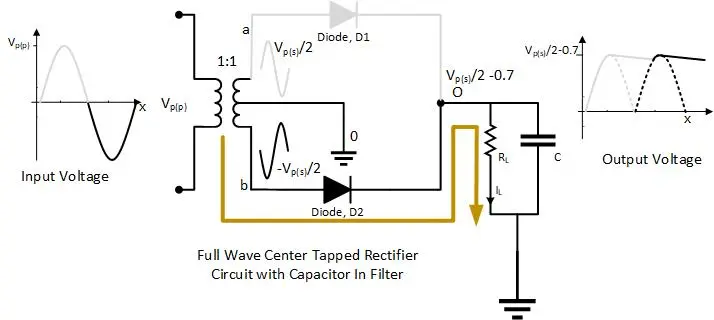
Negative Half Cycle:
For the negative half cycle, diode D2 is forward-biased,d and diode D1 is reverse-biased. The current makes its path through D2 and the load resistor. Same as the previous case, here also, the half part of the secondary winding is driving the load. In both cases, the current through the load is unidirectional or pulsating Direct Current (DC).
Effect of the turn ratio on rectifier output:
Because half of the secondary winding drives the load, only half of the secondary voltage appears across the load in each case. For the transformer ratio of 1:1, the secondary voltage and primary voltage remain the same, so the voltage across the load will be half of the input voltage. To make the full input voltage appear across the load, a transformer ratio should be set to 1:2, considering the diode forward voltage drop, which is 0.7 volts for a silicon diode and 0.3 volts for a germanium diode.
Peak inverse voltage of the diode:
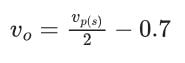
Both diode forward bias and reverse bias are alternated as the sinusoidal voltage changes direction. Each diode should tolerate the maximum reverse voltage, which is called Peak Inverse Voltage (PIV). Consider the positive half cycle, where diode D1 is forward-biased, and analyze diode D2 for PIV. As the diode D1 is forward-biased, the peak voltage at point O will be
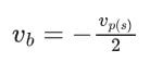
Moreover, the voltage at point b will be
The inverse voltage across the diode D2 will be
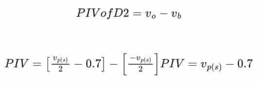
The same procedure can be repeated for the diode D1 peak inverse voltage equation.
Average Output of the Rectifier:
During the complete sinusoidal input cycle, the output of the center-tapped rectifier repeats itself twice. In other words, the time-period of the output is π instead of 2π. Therefore, the average of the output waveform will be
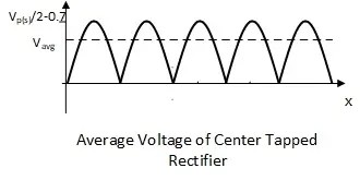
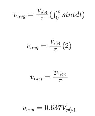
Notice that the average voltage of the center-tapped rectifier is twice that of the half-wave rectifier, which is 0.32.
Ripple factor of the rectifier:
The ripple factor shows the effectiveness of the filter and is defined as
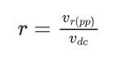
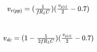
Where vr(pp) is the ripple voltage (peak-peak) and vdc value of the filtered output. The formulas for vdc and vr(pp) are given below
- Charging EV: A Beginner’s Guide to Electric Vehicle Ownership
- 3D Scanning in Industrial Inspection and Engineering Applications
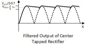
Notice that the frequency of the rectifier’s output waveform is twice the input frequency.
Conclusion
- The tapped rectifier converts both halves of the AC input cycle into a DC output
- The rectifier uses a tapped transformer and two diodes, and the tapping is grounded
- The average output of the center-tapped rectifier is twice that of a half-wave rectifier
- The ripple voltage is less than that of a half-wave rectifier
- The output voltage can be controlled with a change in the turn ratio
Short Answer Questions:
Is a transformer required with a center-tap full-wave rectifier?
Yes, a transformer is required for the specific type of full-wave rectifier called a center-tap full-wave rectifier. In this configuration, the transformer’s secondary winding has a center tap, and two diodes are used to rectify the AC voltage. This arrangement allows both halves of the AC cycle to be utilized for rectification.
Why are bridge rectifiers preferred over full-wave center-tapped rectifiers?
The bridge rectifiers are preferred over the full-wave center-tapped rectifiers because of the center-tapped transformer requirement. Transformers are expensive circuit elements; therefore, they are avoided.
full-wave center tap – is it possible to connect a third diode on the center tap before you make it as ground? in reverse polarity direction of course, but i’m wondering what’s going to be the Vo of this configurations, and maybe you can connect also a filter cap on it with reverse polarity as well? thanks from toronto canada
Dear Victor,
It’s not possible to connect the third diode at the center tap, because the current in the center tap is changing its direction every cycle. Please look a the positive half cycle and negative half cycle highlighted current path.
By doing so, the rectifier will no more a full-wave rectifier it will become a half-wave rectifier.
How do you calculate the needed capacitor for filtering of a power supply that uses a center tapped t rectifier?
I have same question.
For center-tapped rectifier capacitors (C) calculation use the formula of vrpp and solve for Capacitance C.
centre tap you are grounding. there is a voltage at centre tap with respect to top end and bottom end of winding. ground a potential point safe ???
please clarify
Yes, of course, it’s safe and practical.
Grounding the center tap provides a stable reference point and helps in creating a symmetrical AC waveform during the rectification process. However, be aware of the potential differences between the center tap and other points in the circuit.