In the previous article, we discussed a center-tapped full-wave rectifier. This requires a center-tapped transformer, and the peak output of the rectifier is always half of the transformer’s secondary voltage. The full-wave bridge rectifier with a capacitor filter has no such requirement or restriction.
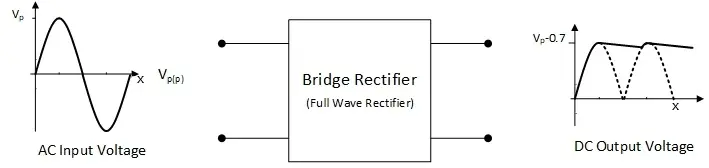
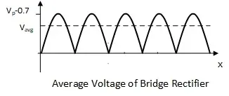
The average output of the bridge rectifier is about 64% of the input voltage. The Bridge-type full-wave rectifier can convert an AC to DC by means of four diodes. The diodes are connected in such a configuration that the output peak voltage remains equal to the secondary of the transformer peak. In each half-cycle, a set of two diodes conducts and blocks the current alternately. In contrast to the center-tapped rectifier, the Bridge rectifier needs four diodes instead of two, which becomes expensive.
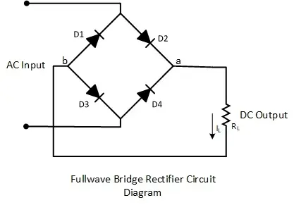
Bridge Rectifier Schematic:
As the name suggests, the configuration of four diode connections forms a bridge. At the two corners of the bridge, the input AC voltage is applied, and at the other two corners of the bridge, the output DC voltage is collected.
Working of Full Wave Bridge Rectifier with Capacitor Filter
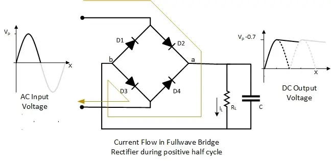
Positive Half Cycle of Rectifier
During the positive cycle of the AC input, the upper corner of the bridge is comparatively positive, where diodes D1 and D2 are connected. In addition, the lower corner of the bridge is comparatively negative, where diodes D3 and D4 are connected.
- Charging EV: A Beginner’s Guide to Electric Vehicle Ownership
- 3D Scanning in Industrial Inspection and Engineering Applications
In this situation, diode D2 is forward-bias as its anode is connected to a comparatively higher potential. Diode D1 is reversed-biased as its cathode is connected to a comparatively higher voltage. Similarly, at the lower corner, diode D3 is forward-biased as its cathode is connected to a comparatively lower voltage, and diode D4 is reverse-biased as its anode is connected to a comparatively higher voltage.
For the positive cycle, the current flows from the upper corner of the bridge through diode D2, then through the load resistor from point A towards point B and diode D3, completing its path to the lower corner.
Negative Half Cycle of Rectifier:
During the negative cycle of the AC input, the upper corner of the bridge is comparatively negative, where diodes D1 and D2 are connected. In addition, the lower corner of the bridge is comparatively positive, where diodes D3 and D4 are connected.
In this situation, diode D1 is forward-biased as its cathode is connected to a comparatively lower potential, and diode D2 is reverse-biased as its anode is connected to a comparatively lower voltage. Similarly, at the lower corner, diode D4 is forward-biased as its anode is connected to a comparatively higher voltage, and diode D3 is reverse-biased as its cathode is connected to a comparatively higher voltage.
For the negative cycle, the current flows from the lower corner of the bridge through diode D4, then through the load resistor from point A towards point B and diode D1, completing its path to the higher corner.
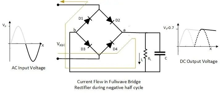
Note that during both cycles, the current flow in the load is from point A towards point B, and the current is unidirectional, like DC rather than AC.
Average Output of the Bridge Rectifier
- Basic Electrician Test – Check Your Electrical Knowledge
- Complete Guide to Circuit Analysis in Electrical Engineering
For a complete input sinusoidal cycle, the output of the full-wave bridge rectifier repeats twice. In other words, the time period of the complete cycle of the output is π instead of 2π. So, the average of the output waveform will be

Peak Inverse Voltage of the Bridge Rectifier:
Consider a positive half cycle, where D2 and D3 are forward-biased and D1 and D4 are reverse-biased. Peak inverse voltage appears across the diodes D1 and D4. The inverse voltage across the diode D4 can be determined by applying KVL to the loop.

Ripple factor of the rectifier:
The ripple factor shows the effectiveness of a full-wave bridge rectifier with a capacitor filter and is defined as

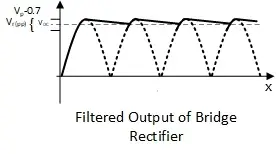
Where vr(pp) is the ripple voltage (peak-peak) and vdc value of the filtered output. The formulas for vdc and vr(pp) are given below.

Notice that the output waveform of the rectifier shows that the frequency of the output voltage is twice the input voltage.
Calculating the Output Voltage of a Full-Wave Rectifier with Capacitor Filter
To determine the output voltage of a full-wave rectifier paired with a capacitor filter, you need to use a specific formula and consider several components of the circuit.
Understanding Full-Wave Rectifiers and Bridge Rectifiers
When diving into the world of rectifiers, it’s essential to grasp the differences between full-wave rectifiers and bridge rectifiers. While they share the function of converting alternating current (AC) into direct current (DC), their structure and application vary.
Full-Wave Rectifiers
- Types:
- Center-Tap Full-Wave Rectifier: Utilizes a center-tap transformer.
- Components:
- Requires two diodes and a transformer with a center tap on the secondary winding.
- Operation:
- Converts both halves of the AC waveform into DC. The center tap allows each diode to conduct during one-half of the input cycle.
- Efficiency:
- Capable of high conversion efficiency but requires a specific transformer setup.
- Cost and Complexity:
- More complex due to the necessity of a center-tapped transformer, potentially increasing cost.
Bridge Rectifiers
- Components:
- Consists of four diodes arranged in a bridge configuration.
- Operation:
- Provides full-wave rectification without the need for a center-tap transformer. Two diodes conduct during each half-cycle of the AC input.
- Efficiency:
- Generally efficient with better transformer utilization compared to center-tap versions.
- Cost and Simplicity:
- Easier and often more cost-effective, as it doesn’t require a special transformer. The use of four diodes might increase diode cost slightly, but overall, it’s a simpler solution.
Conclusion
- The average output of the Bridge rectifier is twice that of a half-wave rectifier.
- The bridge rectifier converts both halves of the AC input cycle into DC output.
- The rectifier uses four diodes, which is why it is considered expensive.
- The ripple voltage of a full-wave bridge rectifier with a capacitor filter is less than that of a half-wave rectifier.
Limitations of a Full-Wave Rectifier with Capacitor Filter
While the bridge rectifier offers improved efficiency and reduced ripple voltage, it is not without its limitations:
- Higher Voltage Input Requirement: This circuit demands a higher voltage input compared to a half-wave rectifier, which can be a significant limitation in applications with restricted input voltage.
- Residual Ripple in Output Voltage: Despite the reduced ripple, some ripple remains in the output voltage. This may not be suitable for applications that require a perfectly smooth DC output.
In summary, while the bridge rectifier offers numerous advantages over its half-wave counterpart, it is essential to consider these limitations when selecting a rectifier for specific applications.
Short Answer Questions:
Why add capacitors to a full-wave bridge rectifier?
The capacitor at the full-wave bridge rectifier smooths the pulsating DC and reduces the ripples. As shown in the above formula, the ripple voltage is reduced by increasing the capacitor value.
What does the transformer do in a full-wave bridge rectifier?
In a full-wave bridge rectifier, the transformer steps down or steps up the incoming alternating current (AC) voltage, providing the necessary voltage for the rectification process to convert AC to DC.
What does the transformer do in a full-wave bridge rectifier?
In the case of the same transformers used in the center-tapped and bridge rectifier, the bridge rectifier output must be higher. It’s because that bridge rectifier allows it to utilize both halves of the input AC signal, resulting in a more efficient conversion of AC to DC.
How to determine values for filter capacitors for rectifier circuits?
Determine filter capacitor values for a rectifier circuit by calculating load current, choosing an acceptable ripple voltage, and selecting capacitance based on frequency, ensuring voltage ratings and physical constraints are met.
When negative half cycle potential of top wire is -Vp .Capacitor has potential of Vp . Is the PIV of D2 = 2Vp…?am i right?
Yes
Good Question.
As far as, the capacitor and load are connected in parallel, the voltage of point a will be same as the capacitor. Where the anode of diode D2 will be at zero volts, so the PIV will be equal to Vp.
I understand the purpose of the four diodes but what is the purpose of the capacitor?
The capacitor filters the fluctuation of the DC voltage.
In a bridge full wave capacitor filtered rectifier circuit, I thought the available current was less than the available current for a 2-diode full wave system.
In other words, if I have a 17 VAC winding capable of 1/2 Amp, what would be the available DC current after the capacitor filter, using a full wave bridge rectifier with a large capacitance (which would result in only 5% ripple) ???
What is the NPN transistor?
NPN is a type of transistor
Yes
Would a failing capacitor (if only marginally) produce a DC induced hum evident at the output stage of an amplifier supplied by a full wave bridge rectifier?