A diode Voltage doubler circuit is an electronics circuit for increasing the voltage peak without using a transformer by utilizing the clamping action. The most common voltage multipliers are double, triple, and quadruple.
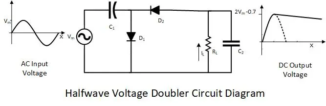
Half-Wave Voltage Doubler Circuit
The load drops voltage in the first half cycle, and in the second half cycle, the voltage level is doubled again; that is why it is called a half-wave voltage doubler. The half-wave voltage doubler uses two diodes and two capacitors.
- Charging EV: A Beginner’s Guide to Electric Vehicle Ownership
- 3D Scanning in Industrial Inspection and Engineering Applications
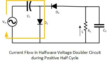
Positive Half Cycle
During the positive half-cycle, the diode D1 is forward-bias to charge the capacitor C1 to the peak voltage of the supply Vs. Where the diode D2 is reverse-biased, and there is no charging current in capacitor C2.

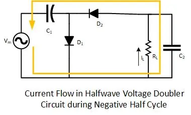
Negative Cycle:
For the negative half cycle, the diode D1 is reverse-biased, and no charging current flows through capacitor C1. Where the diode D2 is forward biased, and the charging current will flow into capacitor C2. The charging current of capacitor C2 will follow the following loop.
Applying KVL at the loop will give us

As Vc1 ≅ Vm, by putting it into the equation

If the load is connected to the output, the capacitor C2 will discharge during the positive half cycle, and then it will charge again in the upcoming negative cycle.
- Basic Electrician Test – Check Your Electrical Knowledge
- Complete Guide to Circuit Analysis in Electrical Engineering
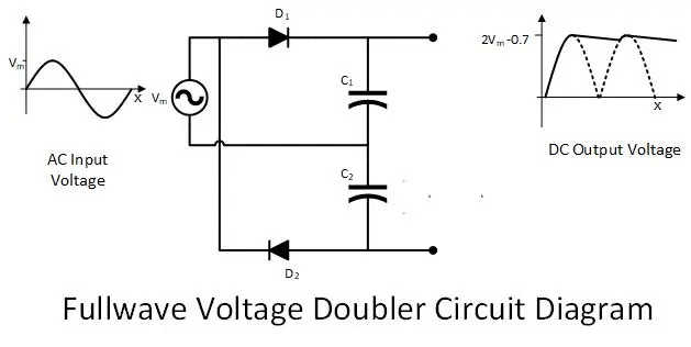
Full-wave Voltage Doubler:
In a Full-wave voltage doubler circuit, the voltage level is maintained doubled in both half cycles. It uses two capacitors and two diodes with a slightly different configuration.
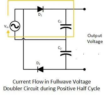
Positive Half Cycle
During the positive half cycle, the diode D1 conducts and charges the capacitor C1 to the supply voltage. Where the diode D2 is reverse-biased, and no current flows through capacitor C2.
Full-wave Voltage Doubler Circuit
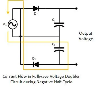
Negative half Cycle
During the negative half cycle, the diode D1 is reverse-biased, and no current flows through capacitor C1. Moreover, the diode D2 is forward-biased, and the capacitor C2 charges the supply voltage.
If no load is connected to the output terminals, the voltage will be twice the input peak voltage. In the case of a load connected, the voltage level of the capacitor C1 will drop below the input peak voltage during the negative half, and the capacitor C2 will drop during the positive half cycle. The peak inverse voltage for both voltage doublers is 2Vm.
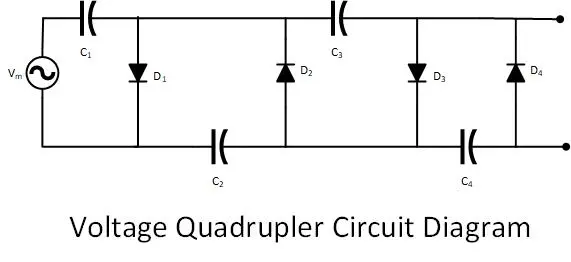
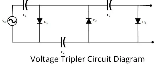
Voltage Tripler and Quadrupler Circuit
Voltage tripler and quadrupler are the extensions of the voltage doubler and increase the voltage level three times and four times, respectively. As per the demand, a capacitor and diode set can increase the voltage level.
Conclusion:
- Voltage multipliers are electronic circuits to increase the voltage peak a few times.
- Voltage Doubler, Tripler, and Quadrupler increase voltage peaks by two, three, and four times, respectively.
If I had for 200 volt capacitors but three of them were 680 microfarad and one of them was 1000 microfarad could I use two in one circuit into in the other and it still work or do they have to be all equal or is it just voltage critical