In the realm of electrical engineering, understanding how to test a Silicon-Controlled Rectifier (SCR) is a valuable skill. Whether you’re a seasoned professional or an enthusiast diving into electronics, mastering this process can save you time and ensure the optimal performance of your circuits. In this guide, we’ll walk you through the steps of testing an SCR using a multimeter, demystifying the process for you.
Materials Required:
- Multimeter: Ensure your multimeter is in working condition and set to measure resistance.
- SCR (Silicon-Controlled Rectifier): The SCR you’re testing should be removed from the circuit for accurate results.
- Pen and Paper: Keep these handy for jotting down measurements and observations.
How to Test SCR with a Multimeter Guide:
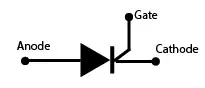
1. Identify SCR Pins:
Before testing, familiarize yourself with the SCR pins. Usually, SCRs have three leads: Anode (A), Cathode (K), and Gate (G). Refer to the datasheet if needed.
2. Set Multimeter to Resistance Mode:
Switch your multimeter to the resistance or ohmmeter mode. This mode allows you to measure the resistance across the SCR terminals.
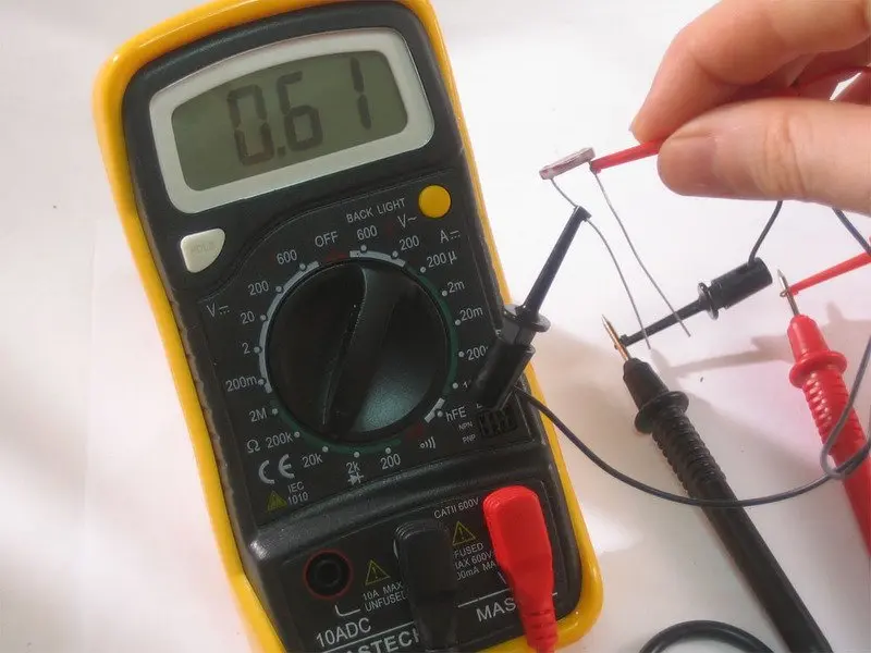
3. Measure Forward Resistance:
Connect the multimeter probes to the Anode (A) and Cathode (K) terminals. A functioning SCR should exhibit high resistance in one direction and low resistance in the other. Note down the readings.
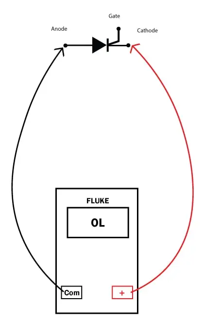
4. Test Reverse Resistance:
Reverse the multimeter probes, connecting them to the Cathode (K) and Anode (A) terminals. Again, observe the resistance readings. A healthy SCR should display high resistance in both directions.
5. Check Gate Triggering:
Now, set the multimeter to measure resistance between the Gate (G) and Cathode (K) terminals. Apply a voltage (follow the SCR’s datasheet for the recommended voltage) across the Gate (G) and Cathode (K) terminals and observe a significant drop in resistance. This confirms the SCR’s ability to conduct when triggered.
6. Record and Analyze:
Take note of all your measurements. Compare them with the SCR’s datasheet specifications. If the readings align, your SCR is likely in good working condition.
Testing on Load Condition
To add an extra layer of assurance, test the SCR under load conditions if possible. Simulate the operating conditions it will face in your circuit. This real-world testing ensures the SCR’s performance aligns with your specific application.
Conclusion:
Congratulations! You’ve successfully navigated the process of testing an SCR using a multimeter. Remember, the key is understanding the expected readings and ensuring your SCR meets those criteria. This knowledge empowers you to troubleshoot, replace faulty components, and optimize the performance of your electronic circuits.
Testing SCR with a multimeter might seem like a complex task initially, but with practice, it becomes second nature. Embrace the learning process, and soon you’ll find yourself confidently tackling SCR testing in your electronic endeavors.