A Zener Diode is a special-purpose diode that is used in reverse bias. A Zener diode is manufactured for a lower and exact reverse breakdown voltage. After the fact that it exhibits the “Zener effect”, which is a specific type of voltage breakdown, the diode is called the “Zener voltage pass Regulator”. Zener voltage pass regulator is the most common use of the Zener diode.
An ordinary diode can reach the reverse bias voltage where the diode will be unable to stop the current flow. That voltage is the reverse breakdown voltage. The reverse breakdown voltage is a destructive and permanent damage phenomenon for an ordinary diode. A special-purpose diode can be designed for working in the reverse breakdown region. It must have an adequate power dissipation ability.
- 3D Scanning in Industrial Inspection and Engineering Applications
- Wearable Electronics: The Future of Smart and Connected Living
Diodes can exhibit two types of breakdowns: Zener breakdown and avalanche breakdown. Avalanche breakdown occurs at a comparatively higher negative voltage and is used to occur in Zener and rectifier diodes. Where Zener breakdown can occur in the Zener diode at a low negative voltage. Near the Zener breakdown voltage, the electric field is too intense to pull out the electrons from the valence band toward the conduction band. The Zener diode operating below 5 volts operates on the Zener breakdown and above the 5 volts operates upon the avalanche breakdown.
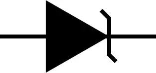
Zener Diode Symbol:
The Zener diode is represented by making small modifications to ordinary diode symbols to make it unique. Both of the symbols are presented here with their direction of current and polarity indicated clearly. Note that the Zener diode is used in reverse bias, where an ordinary diode is used in the forward bias for a typical operation.
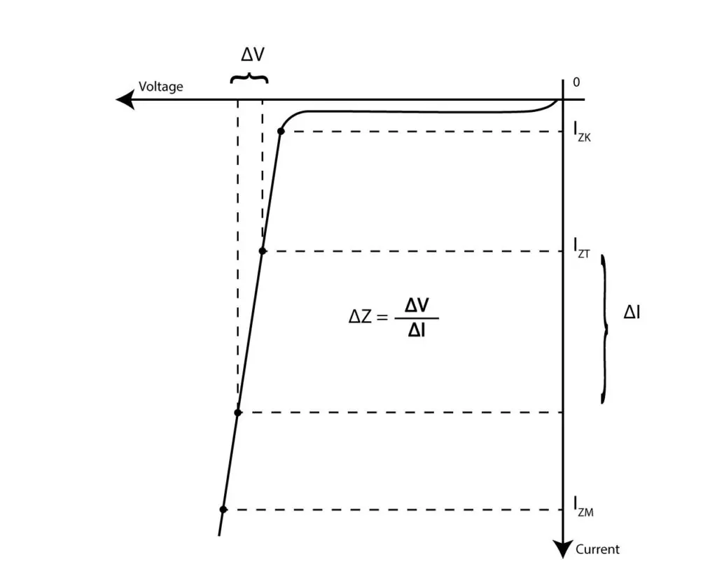
Zener Diode Characteristic Curve:
Zener diode operates in reverse bias, and its forward characteristics are similar to those of a rectifier diode. In reverse characteristics, the breakdown voltage of the Zener diode is comparatively lower than that of an ordinary diode.
As the reverse bias voltage increases, a very small amount of the reverse current flows in the reverse direction. As the reverse voltage is increased, a change in the current curve, just like a “knee”, shows up. The current At this point the b, the breakdown starts, and the impedance at the point is called Zener impedance, and the current is called Zener knee current. With a small further increase in reverse voltage, the voltage drop remains constant, and the current changes drastically which means that impedance decreases.
- Crane Electrical Systems: Safe, Intelligent, and Efficient Operation
- Electrical Installation Guide: Wiring, Protection & Safety Standards
Three points on the characteristics curve are defined by IZK, IZM, and IZT, named as Zener knee current, Zener maximum current, and Zener test current. The nominal voltage across the diode is provided in the datasheet when the current is IZT. Where IZK and IZM are the starting and maximum points of voltage regulation. Outside the specified current range, the doesn’t provide voltage regulation.
Zener Voltage Pass Regulator:
Once breakdown occurs in the Zener diode voltage regulator, a small amount of increase in voltage makes a huge change in current, and the voltage drop across the diode is constant. A small amount of current IZK should be maintained to keep the diode in the breakdown region. The current IZK is the amount of reverse current at the knee of the characteristic curve. A reverse current above a point IZM should be avoided for the safe operation of the diode otherwise the diode may be damaged.
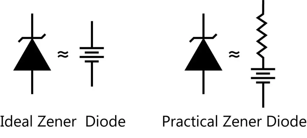
Zener Equivalent Circuit:
An ideal Zener diode in a reverse breakdown equivalent circuit contains a DC voltage source that has a constant voltage drop across it. For a practical Zener diode in reverse breakdown equivalent circuit contains a DC voltage source with a series impedance whose voltage drop across the terminal changes with changes in current.
Example:
A 1N4736 Zener diode has a test impedance, ZZT of 3.5Ω, where Zener test voltage, VZT of6.8Vv a6.8Vener test current, IZT of 35mA, and Zener knee current, IZK of 1mA. What is the voltage across the terminals of the diode when the current is 50mA?
Solution:
The change in the current will for the current of 50mA is

- Basic Electrician Test – Check Your Electrical Knowledge
- Complete Guide to Circuit Analysis in Electrical Engineering
The change in voltage due to an increase in the current above the test current causes the Zener terminal voltage to increase. So, the change in voltage will add to the test voltage, and the voltage at 50mA will be

Conclusion:
- Zener diode works under the reverse bias condition, with the ability to bear more power than an ordinary diode
- The Zener voltage pass regulator regulates the voltage between the current ranging from the Zener knee to the Zener maximum current.