Silicon Controlled Rectifiers (SCRs) are widely used in electronic circuits for their ability to control the flow of electric current. However, turning off an SCR once it is conducting can be a critical task. In this guide, we will explore various methods to properly turn off an SCR and discuss the importance of each approach.
How to Turn Off an SCR (Turn-Off / Commutation Methods)
An SCR can be turned ON by applying a suitable gate pulse, but turning it OFF requires a different process. Unlike a conventional transistor, a standard SCR cannot normally be turned OFF by removing its gate signal.
To turn OFF an SCR, its anode current must fall below the holding current. It must also have sufficient time to recover its forward-blocking ability before forward voltage is reapplied.
The process of turning OFF an SCR is called commutation.
There are two main methods of turning OFF an SCR:
1. Natural Commutation (Line Commutation)
Natural commutation is the simplest method of turning OFF an SCR. It is commonly used in AC circuits.
In an AC supply, the current naturally decreases to zero at the end of each half-cycle. When the SCR current falls below its holding current, the SCR stops conducting.
The reverse voltage appearing across the SCR during the next half-cycle helps it recover its forward-blocking capability.
How natural commutation works:
- A gate pulse triggers the SCR, allowing current to flow through the load.
- As the AC waveform approaches its zero crossing, the load current decreases.
- When the anode current falls below the holding current, the SCR turns OFF.
- The reverse voltage during the next half-cycle provides the required recovery condition.
Natural commutation is commonly used in AC power controllers, controlled rectifiers, and AC motor control circuits.
2. Forced Commutation
Forced commutation is used when an SCR operates on a DC supply or when the circuit current does not naturally fall to zero.
Unlike AC circuits, a steady DC supply does not provide a natural current zero crossing. Therefore, an additional circuit is required to turn OFF the SCR.
A forced commutation circuit uses external components such as capacitors, inductors, and auxiliary switching devices to reduce the SCR current below its holding current or apply a reverse voltage across it.
How forced commutation works:
- The main SCR is triggered and starts conducting current through the load.
- A commutation circuit is activated using an auxiliary SCR or another switching arrangement.
- A charged capacitor or an LC network produces a reverse current or reverse voltage across the main SCR.
- The anode current falls below the holding current.
- The SCR remains reverse-biased long enough to recover its forward-blocking ability.
Forced commutation is commonly used in DC choppers, inverter circuits, and DC motor control systems.
Types of Forced Commutation
Forced commutation is traditionally classified into five main classes:
- Class A – Load Commutation: The load and resonant circuit create an oscillating current that naturally falls to zero.
- Class B – Resonant-Pulse Commutation: An LC circuit produces a reverse current pulse to turn OFF the SCR.
- Class C – Complementary Commutation: Two SCRs are used to turn each other OFF through a commutation capacitor.
- Class D – Auxiliary Commutation: An auxiliary SCR and capacitor generate the reverse voltage required to turn OFF the main SCR.
- Class E – External-Pulse Commutation: An external pulse source applies reverse voltage across the SCR.
These methods use different circuit arrangements, but their main purpose is the same: to reduce the SCR current below its holding current and provide sufficient recovery time.
Difference Between Natural and Forced Commutation
| Feature | Natural Commutation | Forced Commutation |
|---|---|---|
| Supply | AC supply | Commonly DC supply |
| Turn-off method | Natural current zero | External commutation circuit |
| Extra components | Usually not required | Usually required |
| Circuit complexity | Simple | More complex |
| Applications | AC controllers and rectifiers | DC choppers and inverter circuits |
Important Conditions for Turning OFF an SCR
Remember these three important points:
- The anode current must fall below the holding current.
- The SCR must have sufficient turn-off time to recover its forward-blocking capability.
- Removing the gate pulse alone cannot turn OFF a conventional SCR.
Note: A Gate Turn-Off Thyristor (GTO) is different from a conventional SCR because it can be turned OFF by applying a suitable negative gate current.
Natural Commutation Method:
Natural commutation is a method where the SCR turns off automatically when the current through it decreases to zero. This process is achieved by allowing the external circuit to reverse-bias the SCR. In other words, natural commutation relies on the external conditions of the circuit to turn off the SCR.
To optimize turning off an SCR using natural commutation, ensure that the load conditions and circuit design support this method. Properly design the circuit to facilitate a smooth transition from conducting to non-conducting states.
Gate Turn-Off Method:
The gate turn-off method involves actively controlling the SCR’s gate signal to force it into a non-conducting state. By applying a negative pulse to the gate terminal, the SCR can be turned off, regardless of the current flowing through it.
For optimal results, carefully design the gate control circuitry to provide precise and well-timed pulses. Ensure that the pulse duration and amplitude are within the SCR’s specifications to guarantee a reliable turn-off process.
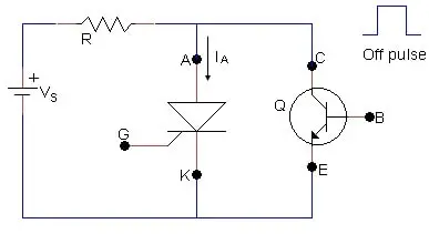
Forced Commutation Method:
Forced commutation is a technique that uses external circuitry to actively turn off the SCR. This method involves introducing a reverse voltage across the SCR during its conduction period. Common forced commutation circuits include the use of commutation capacitors and inductors.
To enhance the effectiveness of forced commutation, select appropriate component values and optimize the circuit layout. A well-designed forced commutation circuit can significantly improve the speed and reliability of turning off an SCR.
Soft Turn-Off Techniques:
Soft turn-off techniques focus on reducing the rate of change of voltage or current during turn-off to minimize stress on the SCR. These methods include the use of snubber circuits, which incorporate resistors, capacitors, and inductors to control the switching dynamics.
To optimize soft turn-off techniques, carefully choose the snubber components based on the application requirements. Properly sized and configured snubber circuits can enhance the SCR’s reliability and reduce the likelihood of damage during turn-off.
Intelligent Control Systems:
Intelligent control systems utilize advanced algorithms and feedback mechanisms to dynamically adjust the turn-off process based on real-time operating conditions. These systems can optimize turn-off timings and minimize stress on the SCR, enhancing its overall performance and reliability.
To implement intelligent control systems, incorporate microcontrollers or programmable logic controllers (PLCs) that can continuously monitor and adjust the turn-off parameters. This approach provides a high level of customization and adaptability to varying operating conditions.
Conclusion:
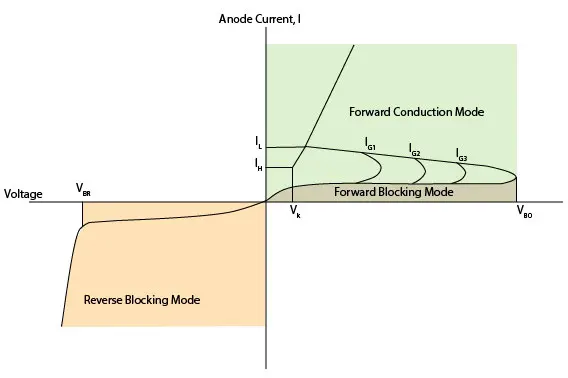
Properly turning off an SCR once it is conducting is essential for maintaining the reliability and efficiency of electronic circuits. Whether using natural commutation, gate turn-off, forced commutation, soft turn-off techniques, or intelligent control systems, each method plays a crucial role in optimizing the SCR’s turn-off process. By carefully considering these methods and tailoring them to specific applications, engineers can determine whether the SCR is in forward-blocking or reverse-blocking mode to turn off conduction.
FAQs
1. How to Turn Off an SCR?
A conventional SCR can be turned OFF by reducing its anode current below the holding current and allowing sufficient recovery time. In AC circuits, this happens naturally when the current reaches zero, a process called natural commutation. In DC circuits, an external commutation circuit is generally required to reduce the current or apply reverse voltage.
2. What is SCR in Hindi?
SCR का पूरा नाम Silicon Controlled Rectifier (सिलिकॉन नियंत्रित दिष्टकारी) है। यह एक चार-लेयर और तीन-टर्मिनल वाला सेमीकंडक्टर डिवाइस है, जिसका उपयोग विद्युत धारा को नियंत्रित करने के लिए किया जाता है। इसके तीन टर्मिनल Anode, Cathode और Gate होते हैं। Gate पर उचित पल्स देने से SCR चालू होता है और करंट को नियंत्रित करता है।