
Discover how to check FET transistors using a multimeter. This guide provides a detailed step-by-step process to ensure accurate testing FET Transistor and gate-source current with zero gate voltage IDss of the FET transistor.
Understanding FET Transistors
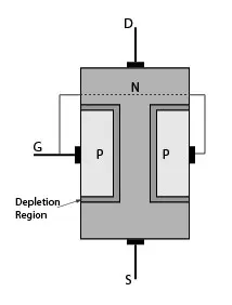
Field-effect transistors (FETs) are crucial in electronic circuits, regulating current flow. Learn about the basics of FET transistors and why testing them is essential.
Testing FET Transistor with Multimeter:
Material Required
Before proceeding, gather the necessary tools:
- Multimeter
- Alligator clips (optional)
Step-by-Step Guide
Preparation:
Ensure the FET is disconnected from the circuit. Identify and note the FET’s pin configuration using its datasheet.
Set Multimeter to Diode Test Mode:
Turn the multimeter on and select the diode test mode. This mode helps assess the FET’s forward and reverse bias conditions.
Connect the Multimeter to the FET Pins:
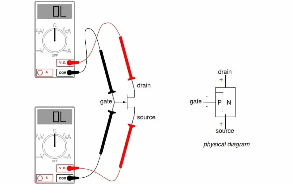
Connect the multimeter probes to the FET’s gate, drain, and source terminals. Follow the datasheet to identify these terminals correctly.
Test Gate-to-Source (GS) Voltage:
Place the positive probe on the gate and the negative probe on the source. A reading should indicate an open circuit (no continuity).
Test Gate-to-Drain (GD) Voltage:
Move the negative probe to the drain while keeping the positive on the gate. Again, expect an open circuit reading.
Test Source-to-Drain (SD) Voltage:
Finally, shift the positive probe to the source while maintaining the negative on the drain. This should result in continuity, indicating a low resistance.
Interpreting Results
- Good FET: All readings match expectations.
- Shorted FET: Continuity across all terminals.
- Open FET: No continuity across any terminals.
How to Test IDss of a FET Transistor?
IDSS (Drain-Source Current with Zero Gate Voltage) is a key parameter for FETs, especially for JFETs (Junction Field-Effect Transistors). Testing IDSS involves measuring the drain current when the gate-source voltage is zero. Here’s a general guide:
Materials Required:
- Multimeter: Set to the current measurement mode.
- FET Transistor: Remove it from the circuit for testing.
- Power Supply (Optional): Some tests may require applying a voltage.
Step-by-Step Guide
Identify the FET Pins:
- For JFETs, which are commonly associated with IDSS, identify the Gate (G), Drain (D), and Source (S) terminals.
Set Up the Test Circuit:
- Connect the Drain (D) terminal to the positive lead of the multimeter.
- Connect the Source (S) terminal to the negative lead of the multimeter.
- Ensure that the Gate (G) terminal is disconnected or left open.
Zero Gate Voltage:
- Make sure the Gate (G) is not connected to anything or is connected to the source terminal for JFETs.
- Measure the drain current (ID) with the multimeter in series with the drain and source terminals.
- The measured current is the IDSS.
Optional: Apply Voltage for Depletion-Mode FETs:
- If your FET is a depletion-mode type, you might need to apply a negative voltage to the gate to the source to achieve IDSS.
- Consult the datasheet for specific instructions regarding gate biasing.
Interpret the Results:
- Compare the measured IDSS with the specifications in the datasheet.
- Ensure that the IDSS falls within the acceptable range for your specific FET.
Remember that testing FET transistor procedures may vary based on the type and model of the FET. Always refer to the manufacturer’s datasheet for accurate information on testing and characterization.