Skip to content

Electric Shocks | Electrical Engineering Tutorials

Practical Electrical Tutorials, Safety, and Industrial Solutions

  • Home
  • Blog
    • Electrical Engineering
    • Electronics Engineering
    • Electrical Installation
    • Solar Energy
    • MCQs
    • Books
  • Graph Plotter
  • Services
    • Forum
    • Calculators
    • Other Services

Voltage Source

A voltage source is a two terminal device providing a constant voltage across its terminals regardless of current flowing through it. A voltage source may be dependent on some circuit variable or may be independent at all.
Explain BJT Transistor construction and working principle

February 25, 2026March 21, 2020 by Gul Faraz
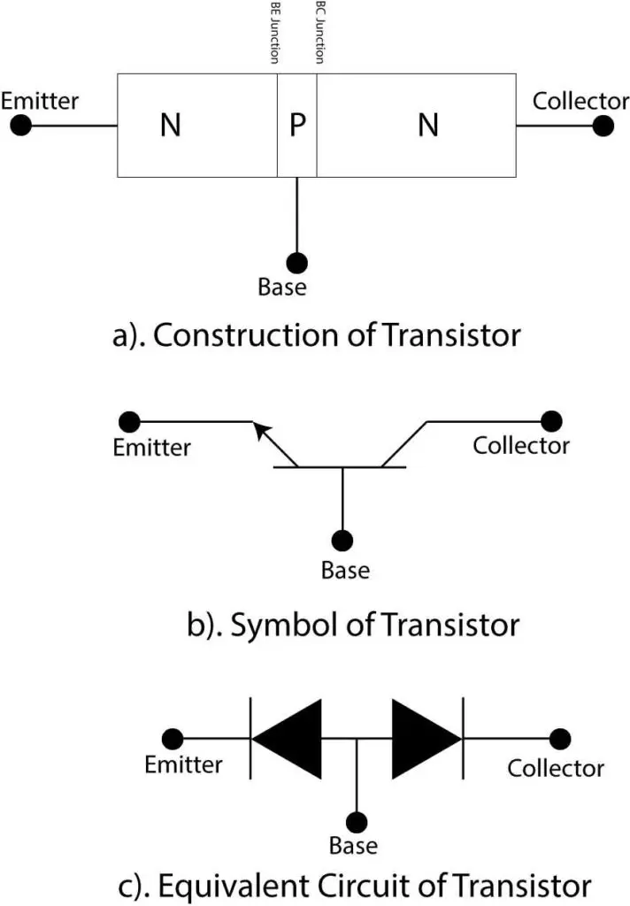
Transistor construction, symbol and equivalent circuit

Explain the working principle and construction of BJT Transistor and Symbol. A transistor can work as digital switch or an amplifier.

Categories Electronics Engineering Tags Current Source, diode, Transistor, Voltage Source

Zener Voltage Pass Regulator Explained with Example

August 6, 2025November 1, 2019 by Gul Faraz
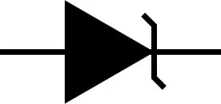
Zener Diode Symbol

A Zener Diode is a special purpose diode used for voltage regulation in reverse bias. Zener diode work under breakdown region for typical operation. A minimum current of Zener knee current must be maintained to keep the voltage regulated.

Categories Electronics Engineering Tags diode, Voltage Source

3 Methods of testing a diode with multimeter and oscilloscope

March 2, 2026August 15, 2019 by Gul Faraz
Testing a diode

Testing a diode with a digital multimeter in two ways, diode testing portion, and ohmmeter. A diode test is considered passed if it shows low resistance/voltage drop on forward bias and high resistance/voltage drop in reverse bias. A diode curve tracer uses an oscilloscope for VI characteristics graph.
Categories Circuit Analysis Tags Current Source, diode, meter, Voltage Source

Diode Voltage Doubler Circuit with Tripler and Quadrupler

February 18, 2026August 9, 2019 by Gul Faraz
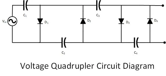
voltage quadrupler

Voltage Multipliers are electric circuits to increase the voltage by a factor of two, three or four in case of Voltage Doubler, Tripler or Quarple respectively. The Voltage multiplier circuit uses capacitors and resistors to enhance the voltage level.

Categories Circuit Analysis Tags Alternating current, capacitor, diode, Voltage Source 1 Comment

Forward Bias Diode and Reverse Bias Diode Characteristic Graph

February 28, 2026December 25, 2018 by Shahab Yousafzai
forward bias and Reverse bias of diode

A diode can be connected in forward and reverse bias with a source. In Forward bias connection, a diode conducts current like a closed switch. Where in reverse bias, a diode blocks current like an open switch.

Categories Electronics Engineering Tags diode, Electronic Devices, Power Electronics, Voltage Source 4 Comments

Difference between Alternating Current and Direct Current

August 8, 2025August 25, 2018 by Shahab Yousafzai
Difference between Alternating Current and Direct Current

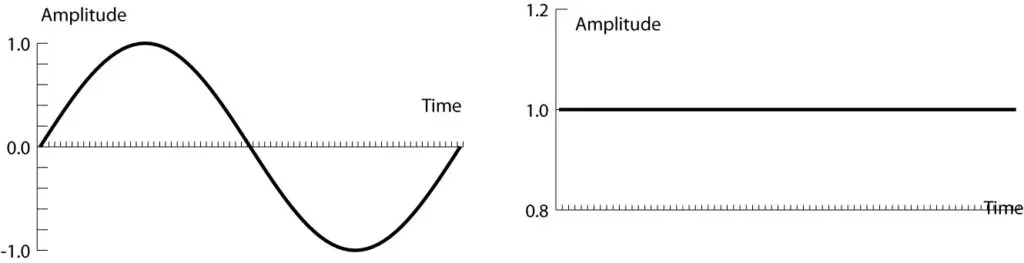
Alternating current (AC) is the type of electrical current which changes its direction and magnitude every moment.

Categories Circuit Analysis Tags Current Source, Voltage Source

How do Capacitors Add in Series: Capacitor in the Series Calculator

October 14, 2026August 6, 2018 by Gul Faraz
Capacitors in Series and parallel

Capacitors can be connected in series to achieve the desired capacitance. The capacitance of series connection decreases and that of parallel connection increases.

Categories Circuit Analysis Tags capacitor, Electrical Engineering Calculators, Parallel Connection, series connection, Voltage Source

Difference between Ideal and practical, Voltage and Current Source

February 28, 2026June 12, 2018 by Gul Faraz
Difference between ideal and practical Source

In contrast to a practical voltage source, an imaginary deal source provide constant voltage regardless of load current because of no internal resistance. While ideal current source provides a constant current regardless of load current.

Categories Circuit Analysis Tags Current Source, Voltage Source 5 Comments

Voltage to Current Source Transformation Theorem

August 8, 2025June 3, 2018 by Gul Faraz
Source Conversion

Source transformation or conversion is a technique to replace a voltage source with a current source for circuit simplification and vice versa.

Categories Circuit Analysis Tags Current Source, Voltage Source

Thevenin Theorem and Example: The Thevenin Equivalent Circuit

February 23, 2026May 29, 2018 by Gul Faraz
Thevenin Equivalent Circuit

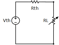
According to Thevenin Theorem, a complex circuit is reduced to two resistor network, Thevenin Resistor, and Load resistor and a Thevenin Voltage source to avoid redundant computation to analyze a frequent changing resistor.

Categories Circuit Analysis Tags Voltage Source
Newer posts
← Previous Page1 Page2

What are you looking for?

Your Account

Log In

You may like to know

  • How to Know When Your Electrical Panel Needs an Upgrade
  • Charging EV: A Beginner’s Guide to Electric Vehicle Ownership
  • 3D Scanning in Industrial Inspection and Engineering Applications
  • Wearable Electronics: The Future of Smart and Connected Living
  • Electrical Safety Test: 10 Quiz MCQs to Check Your Knowledge
  • Basic Electrician Test – Check Your Electrical Knowledge
  • Home EV Charger Installation Guide: Everything You Need to Know
  • Encoder in Robots: Types, Working Principle and Applications
  • The Complete Solar Energy Guide: Design, and Installation
  • Crane Electrical Systems: Safe, Intelligent, and Efficient Operation

Forum Discussion

  • Can I Use a 220V Appliance in the USA?
  • What type of desoldering wick should i use?
  • How much do electricians earn per hour near me
© 2026 Electric Shocks | Electrical Engineering Tutorials • Built with GeneratePress