Difference Between CAT5 and CAT6 Which One is Better
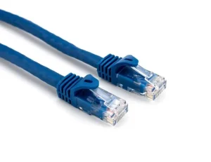
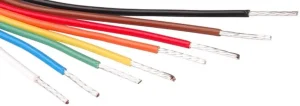
what is the difference between cat5 and cat6, and which cable is better for new house wiring because both categories serve the same way with few differences?
Electric Shocks | Electrical Engineering Tutorials
Practical Electrical Tutorials, Safety, and Industrial Solutions
what is the difference between cat5 and cat6, and which cable is better for new house wiring because both categories serve the same way with few differences?
Every home, at one time or another, for sure, needs an electrician. There is no way home can function for lifetime sans and electricity problems.
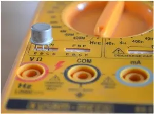
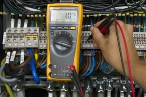
Learn Testing Transistors in Circuits with multimeters, ohmmeter, and curve tracer to test functionality and gain of the transistor.
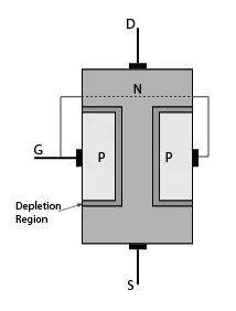
Learn what is a FET? FET Transistor basics, characteristics curves, symbols, types, types of FET, construction, and how a FET works?
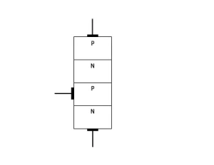
SCR stands for Silicon-controlled rectifier. The SCR is a very important member of the thyristor family. It is more popular than another thyristor family members like TRIAC, and DIAC even though that thyristor is used interchangeably with SCR.
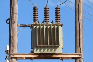
Learn how to figure KVA of a transformer by using the online Transformer KVA Calculator. Also, learn Why Transformer Rating is in KVA Not in KW?
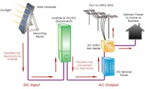
Learn where to use solar power without batteries and where are batteries necessary. Grid-tied and hybrid setup needs no batteries.

A Complete Guide on Part P Course for Beginners for domestic electrician work. covers all domestic electrical installation work, wiring system installation, rewiring, any changes made to the existing electrical system.
learn how to Choose Capacitor Value to Filter Power Supply noise reduction. The basic parameters for choosing a capacitor are voltage, frequency, temperature, and polarization.
Online electrical wire size calculator for AC single phase and DC. Calculate Voltage drop, current, cable size in metric (SI) and British system.