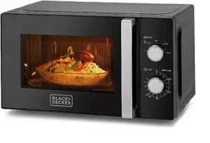
The microwave oven is an electronic device that uses microwave radiation to heat up food, tea, or coffee. A microwave oven is one of the compulsory appliances among others in a home kitchen
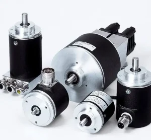
Encoders can be classified in different ways based on the type of motion, technology, number of parameters, etc. The article differentiates between multiple types of encoders.
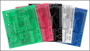
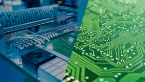
PCB boards are commonly used in every consumer electronics appliance. You may be familiar with PCB’s technical perspective but may be missing some fun facts about PCB boards.
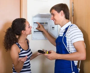
When it comes to electrical repairs, it’s always best to leave it to the professionals. DIY projects can be dangerous, and there’s no room for mistakes when it comes to electricity.
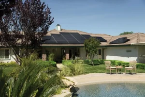
Solar energy is a renewable source of clean energy used to power homes and businesses. As the use of solar electricity increases, electricians and electrical contractors must be able to design and install systems in a way that is safe and efficient for users.
Electrical hazards can kill. When electricity is used improperly in the workplace, it’s not just inconvenient for employees but poses a danger to them.
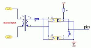
Electrical engineering is a broad field with numerous prospects. It is a branch of study that deals with electronic systems, circuits, and everything else that deals with electricity and its applications.