
Geometric dimensioning and tolerancing is the representation of engineering tolerances that uses GD&T symbols. Engineering drawing and computer-aided design models use GD&T. GD & T symbols communicate nominal geometry and acceptable variation in engineering modeling. The purpose of GD&T is to inform engineering staff about the required degree of accuracy and precision of all the features of the part. Stanley Parker initiated GD&T in the form of a true position.
- Charging EV: A Beginner’s Guide to Electric Vehicle Ownership
- 3D Scanning in Industrial Inspection and Engineering Applications
GD & T Rule:
There are several standards for GD&T symbols.
- The American Standard of Mechanical Engineers (ASME) Y14.5
- The International Organization for Standardization (ISO).
Y14.5 is a single document set of standards for the GD&T symbols. ISO standards are topic-based and categorized.
There are several fundamental rules for dimension and tolerance defined in Y14.5 standards.
- All the dimensions must have a tolerance for every feature that will be subject to variation.
- Scaling is not allowed, but only in certain cases.
- Engineering drawing defines the finished part. Extra dimensions are marked as references.
- The dimension should be applied to the feature that represents the function of the feature. And it should be used for only one interpretation.
- Avoid the explanation of the manufacturing process.
- Arrange all the dimensions and tolerances for maximum readability.
- Lines at a right angle represent the orthogonal angles.
- All the dimensions and tolerances are at 20 degrees C and 101.3kPa unless stated otherwise.
- All the dimensions are valid for the free state unless stated otherwise.
- Dimensions and tolerances are applicable for the length, width, and depth of a feature.
GD & T Symbols:
There is a total of 14 numbers of GD&T characteristics. A separate symbol represents each characteristic. These symbols are the GD&T symbols. Five tolerance categories classify these characteristics as follows.
- Crane Electrical Systems: Safe, Intelligent, and Efficient Operation
- Electrical Installation Guide: Wiring, Protection & Safety Standards
- Form tolerance
- Orientation tolerance
- Location tolerance,
- Runout tolerance
- Location of derived median point tolerance.
Form tolerances control the shape of a feature. Orientation tolerance controls the tilt of a feature. Runout tolerance controls the coaxiality of the surface. Location tolerance controls the location of the surface, center point, axis, and derived median point of a feature.
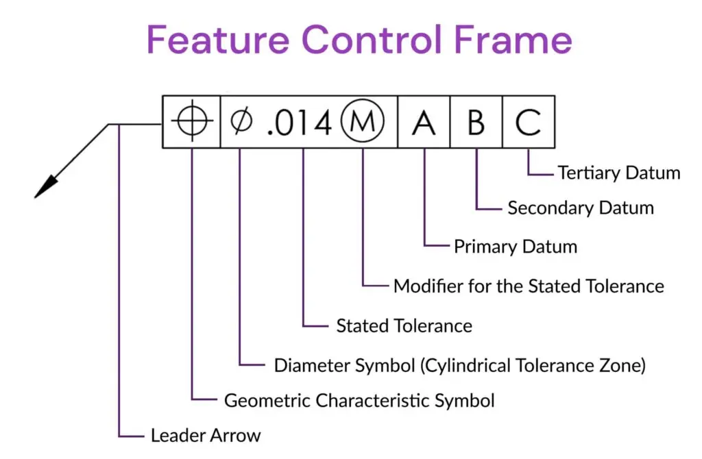
Feature control frame:
The feature control frame represents the requirement of a feature by attaching the frame. The frame contains only one message if multiple messages are required, so multiple frames are attached. The frame contains Geometric characteristics.
- The shape of the tolerance zone
- Feature tolerance
- Feature modifier
- Primary datum
- Secondary datum
- Tertiary datum.
GD & T symbols replace the traditional dimensions and tolerances. The use of proper GD&T improves the quality of production and reduces the resources required for production. It is a standardized design method to communicate them clearly and precisely. Geometric Dimensioning and Tolerancing communicates between the production teams, customers, and suppliers. The assembly is assured from GD & T produced parts, and the production process is repeatable. Geometric Dimensioning and Tolerancing symbols can be inserted in AutoCAD using the tolerance command, which displayss the dialog box