PC817 High-speed optocoupler is an electricity-light-electricity conversion device used for electrical signal transmission with light as the medium. It is composed of a light-emitting source and photoreceiver, both of which are assembled in the same closed casing and are isolated from each other by a transparent insulator. The pin of the light-emitting source acts as the input terminal, and the pin of the photoreceiver acts as the output terminal. The commonly used light-emitting source is LEDs, and the commonly used photoreceivers are photodiodes, phototransistors, etc.
The optocoupler, also known as an optoisolator, features good isolation for input or output electrical signals. The inputted electrical signals drive the LED to emit light with a certain wavelength, and the lights are received by the photoreceiver to generate photocurrent, which is output after amplification. This process realizes the conversion of electricity-light-electricity, thus the optocoupler plays the role of input, output, and isolation. Due to the mutual isolation between the input and the output of the optocoupler and the unidirectional characteristic of the electrical signal, the optocoupler has good electrical insulation and interference resistance.
- Charging EV: A Beginner’s Guide to Electric Vehicle Ownership
- 3D Scanning in Industrial Inspection and Engineering Applications
Basic operating characteristics
1. High common-mode rejection ratio
Inside the optocoupler, since the coupling capacitance between the light-emitting tube and the photoreceiver is very small (within 2pF), the common-mode input voltage has little effect on the output current through the inter-electrode coupling capacitance, so the common-mode rejection ratio is very high.
2. Output characteristics
The output characteristic of the photocoupler refers to the relationship between the bias voltage VCE applied by the photosensitive tube and the output current IC under a certain luminous current IF. When IF=0, the light-emitting diode does not emit light. At this time, the electrode output current of the photosensitive transistor is called dark current, which is generally small. When IF>0, under the action of a certain IF, the corresponding IC is independent of VCE. The change between IC and IF has a linear relationship, and the output characteristics of the optocoupler measured by the semiconductor tube characteristic diagram instrument are similar to the output characteristics of ordinary transistors.
3. Isolation characteristics
(1) Isolation voltage (Vio)
The insulation withstands voltage values between the input and output of the optocoupler.
(2) Isolation capacitance (Cio)
It refers to the capacitance value between the input and output of the optocoupler.
(3) Isolation resistance (Rio)
It refers to the resistance value between the input and output of the optocoupler.
4. Transmission characteristics
(1) Current transfer ratio (CTR)
When the operating voltage of the output tube is a specified value, the ratio between the output current and the forward current of the LED refers to the current transfer ratio.
(2) Rise time and fall time
Under the specified operating condition, the light-emitting diode inputs the pulse wave of the specified current IFP, and outputs the corresponding pulse wave, from 10% to 90% of the amplitude of the front edge of the output pulse; the required time is the pulse rise time. 90% to 10% for the amplitude of the trailing edge of the output pulse, the time required is the pulse fall time.
Optocoupler working
In the following part, Easybom will elaborate on the high-speed optocoupler working principle.
An electrical signal is applied to the input end of the optocoupler to make the light-emitting source emit light. The intensity of the light depends on the magnitude of the excitation current. After the light is irradiated on the packaged photoreceiver, a photocurrent is generated due to the photoelectric effect, which is output by the photoreceiver. The terminal is led out so that the conversion between electricity and electricity is realized.
- Crane Electrical Systems: Safe, Intelligent, and Efficient Operation
- Electrical Installation Guide: Wiring, Protection & Safety Standards
The optocoupler is mainly composed of three parts: light emission, light reception, and signal amplification. The light-emitting part is mainly composed of light-emitting devices, which are generally light-emitting diodes. When the light-emitting diode is applied with a forward voltage, it can convert electrical energy into light energy and emit light. The light-emitting diode can be driven by DC, AC, pulse, and other power sources. But they must be used with a forward voltage. The light-receiving part is mainly composed of photosensitive devices, which are generally phototransistors. Phototransistors use the principle that the reverse resistance of the PN junction changes from large to small under light irradiation when a reverse voltage is applied.
Optocoupler Uses
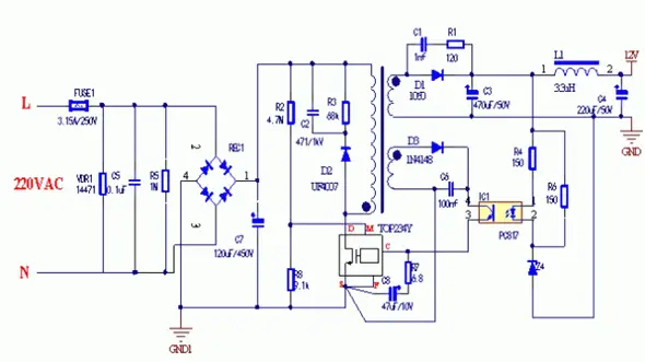
1. Adjusting the voltage of the switching power supply
We know that, as a switching power supply, the power of the optocoupler in its circuit is obtained from the secondary voltage of the high-frequency transformer. Once the output voltage decreases due to various reasons, the feedback current will increase accordingly, and the duty cycle will also increase accordingly, increasing the output voltage; if the output voltage increases, the current will decrease and the duty cycle will decrease, resulting in a decrease in the output voltage. Once the secondary load of the high-frequency transformer is overloaded or the switch circuit is faulty, there is no power supply for the photocoupler. At this time, the optocoupler controls the switch circuit to not start vibrating and finally protects the switch tube from being broken down and burned. Therefore, the optocoupler plays three roles: isolation, providing a feedback signal, and switching in the switching power supply.
- Basic Electrician Test – Check Your Electrical Knowledge
- Complete Guide to Circuit Analysis in Electrical Engineering
The following figure is a switching power supply circuit composed of a PC817 optocoupler and a Zener diode. Some switching power supplies will also form a circuit with higher precision, together with the TL431. Note that this optocoupler is generally linear.
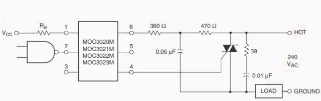
2. Optocoupler as a Switch in AC
Because the optocoupler has unidirectional transmission, and the input end and the output end are electrically isolated, the output signal has no effect on the input end, so it is widely used in various isolation circuits. In power electronics, it is often used to form an isolation circuit with strong anti-interference ability, together with the TIRAC, as shown in the figure below. Pay attention to increasing the current limiting resistance and adding an RC absorption circuit or a varistor in parallel to the output load, which helps to protect the load.
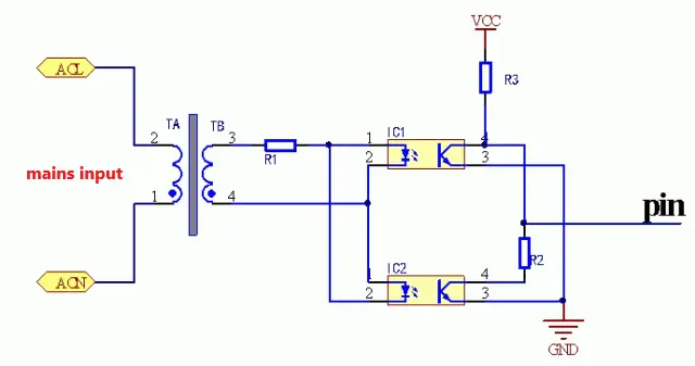
3. Zero-Crossing Detection
Zero-crossing can be realized in many ways, including two diodes in series or conversion by optocouplers. As shown in the figure below, two optocouplers and an AC input are used, and two optocouplers are connected in reverse parallel. In the negative half cycle, the two optocouplers are turned on respectively. When the mains are not at the zero-crossing point, only one optocoupler is turned on. At this time, the output is low. When the mains turn to the zero-crossing point, both optocouplers are turned off. At this time, due to the action of R3, the pin outputs a high level, so that a pulse signal with a period of 10ms is obtained at the output end. Since this circuit is isolated by an optocoupler, this zero-crossing detection circuit is safer than the one with diodes in series.
4. Other Applications
In addition to the three circuits above, the optocoupler can also be used in other circuits, including trigger circuits, logic circuits, pulse amplifier circuits, etc.
What is a High-Speed Optocoupler?
Like the optocoupler, it assembles the light-emitting diode and the phototransistor. It uses the light signal to transmit information and realizes the electrical-optical-electrical transmission of the circuit signal (photoelectric coupling circuit). It is for the input of the circuit to be completely isolated from the electricity, which realizes the electrical isolation of the input and output ports and improves its anti-interference ability, reliability, and stability. This information transfer method is superior to all general solutions that use transformers and relays as isolation for signal transfer, but its advantage lies in high speed; that is, the transmission speed of the signal is fast, which is very common in design that requires the transmission of the signal.
High-Speed Optocoupler Applications
- It can be used for PLC high-speed counter, servo motor control, rotary encoder control, grating ruler output, and signal conversions such as PLC and single-chip pulse; PLC, servo motor control system anti-interference processing; various standard and non-standard pulse signal mutual rotation; Arbitrary waveform (sine wave, triangle wave, irregular waveform) to square wave pulse signal and so on.
- In the switching circuit, it is often required to have good electrical isolation between the control circuit and the switch, which is difficult for ordinary electronic switches but is easy to achieve with it.
- It is used for a bistable output circuit because the light-emitting diodes can be connected in series with two emitter loops, which can effectively solve the problem of isolation between the output and the load.
- Constitute various logic circuits. Because its anti-interference performance and isolation performance are better than those of transistors, the logic circuits formed by it are more reliable.
- Applied to digital circuits, it can amplify the pulse signal.
- It is used in high-voltage control, replacing transformers replacing contact relays, and in A/D circuits and other occasions.
- It is used for bistable output circuits. Since the light-emitting diodes can be connected in series with two emitter loops, the problem of isolation between output and load can be effectively solved.
- Applied in linear circuits, it has high linearity and excellent electrical isolation performance.