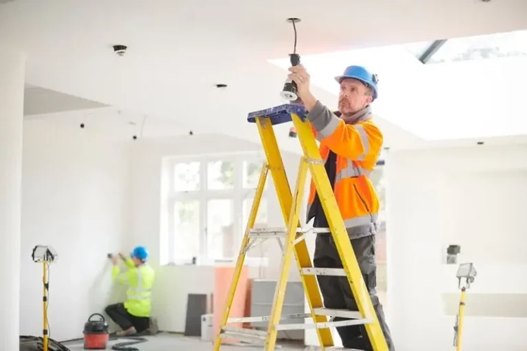
Electrical installation is the backbone of every safe and functional building. Whether it’s a residential home, commercial facility, or industrial plant, proper wiring, protection devices, and grounding systems determine not only performance but also safety and compliance. A well-designed installation prevents electrical shocks, fire hazards, equipment damage, and costly downtime.
This comprehensive guide walks through wiring systems, cable sizing, protection devices, distribution boards, earthing methods, load calculations, and safety standards. If structured correctly, this knowledge becomes the foundation for practical fieldwork and technical expertise.
Fundamentals of Electrical Installation
Electrical installation refers to the complete system of conductors, protective devices, switching equipment, and accessories used to distribute electrical power from the source to end loads.
A complete installation includes:
- Service connection
- Energy meter
- Distribution board
- Circuit breakers
- Wiring circuits
- Earthing system
- Final loads (lighting, sockets, appliances)
The primary objectives of any installation are:
- Safety
- Reliability
- Efficiency
- Compliance with standards
Every installation must ensure current flows safely from the supply to loads and returns without leakage, overheating, or short circuit.
Types of Wiring Systems
Choosing the correct wiring system depends on building type, load demand, environmental conditions, and budget.
1. Cleat Wiring
Temporary wiring method using porcelain cleats. It is rarely used today except for temporary installations.
2. Batten Wiring
Cables are fixed on wooden battens using clips. Suitable for dry indoor environments but less common in modern practice.
3. Casing and Capping Wiring
Wires are enclosed in a wooden casing covered by a cap. This method has mostly been replaced by conduit systems.
4. Conduit Wiring (Most Common)
Conduit wiring is widely used in residential and commercial buildings. It offers:
- Better mechanical protection
- Fire resistance
- Long service life
- Neat appearance
Conduit systems can be:
- Surface conduit
- Concealed conduit
Concealed conduit wiring is preferred in modern installations for aesthetics and safety.
Electrical Cables and Conductor Selection
Cable selection is critical in preventing overheating and voltage drop.
Factors affecting cable sizing:
- Load current
- Length of run
- Installation method
- Ambient temperature
- Voltage drop limits
Copper is the most common conductor due to:
- High conductivity
- Mechanical strength
- Corrosion resistance
Aluminum is used in larger installations due to cost efficiency.
Common Residential Cable Sizes
- 1.5 mm² – Lighting circuits
- 2.5 mm² – Socket outlets
- 4–6 mm² – Air conditioners and heavy loads
- 10 mm²+ – Main supply cables
Undersized cables cause overheating. Oversized cables increase cost unnecessarily. Proper load calculation ensures balance.
- Crane Electrical Systems: Safe, Intelligent, and Efficient Operation
- Electrical Installation Guide: Wiring, Protection & Safety Standards
Load Calculation in Electrical Installation
Load calculation determines the total current demand of a building.
Basic formula:
Current (I) = Power (P) / Voltage (V)
For example:
If total connected load = 5000 W
Supply voltage = 230 V
I = 5000 / 230 = 21.7 A
After calculation:
- Add diversity factor
- Include future expansion margin (20–30%)
- Select an appropriate breaker and cable
Load calculation ensures that:
- Breakers do not trip unnecessarily
- Cables operate within safe limits
- Voltage drop remains acceptable
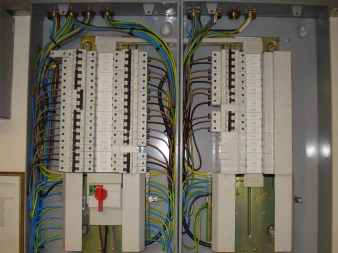
Distribution Boards (DB)
The distribution board is the control center of an installation.
It distributes incoming power into individual circuits and provides protection.
Main Components of a DB
- Main isolator
- MCBs
- RCCB or RCD
- Bus bars
- Neutral link
- Earth bar
Modern installations use modular distribution boards with DIN rail-mounted breakers.
- Complete Guide to Electronics Engineering
- Traction Control Sensor TCS: Working and Common Fault Signs
Types of Distribution Boards
- Single-phase DB
- Three-phase DB
Residential buildings typically use single-phase DBs, while commercial installations use three-phase systems for balanced load distribution.
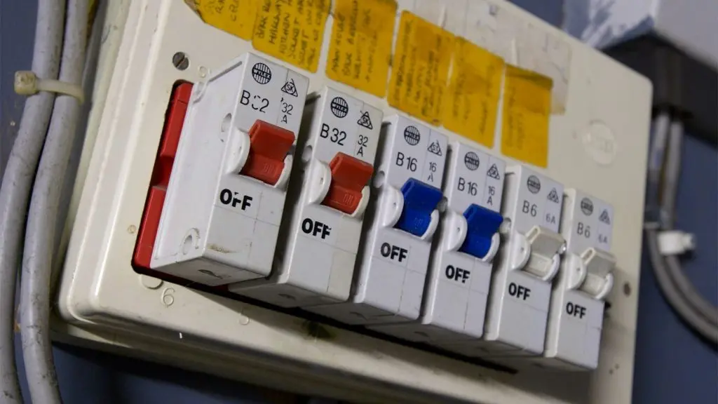
Protection Devices in Electrical Installation
Protection devices prevent damage caused by overcurrent, short circuits, and earth leakage.
Miniature Circuit Breaker (MCB)
MCB protects against:
- Overload
- Short circuit
It automatically disconnects the supply when the current exceeds the rated limit.
Residual Current Circuit Breaker (RCCB)
RCCB protects against:
- Earth leakage
- Electric shock
It detects an imbalance between phase and neutral current.
RCBO
Combines MCB and RCCB in one unit.
MCCB
Used in higher capacity installations such as industrial systems.
Correct selection of protection devices ensures safety without nuisance tripping.
Earthing System
Earthing is one of the most critical components of electrical installation.
It provides a low-resistance path for fault current to flow into the ground.
Purpose of Earthing
- Protect humans from shock
- Protect equipment from damage
- Stabilize voltage levels
- Ensure proper operation of protection devices
Types of Earthing Systems
- Plate Earthing
- Pipe Earthing
- Rod Earthing
- Strip Earthing
Pipe earthing is commonly used in residential installations due to cost-effectiveness and reliability.
Earth Resistance
Ideal earth resistance should be:
- Less than 1 ohm for industrial
- 1–5 ohms for residential
High earth resistance reduces protection effectiveness.
Single Line Diagram (SLD)
A single-line diagram represents the electrical system using simplified symbols.
It includes:
- Source
- Main breaker
- Distribution board
- Sub-circuits
- Earthing points
SLDs help engineers:
- Plan installations
- Troubleshoot faults
- Ensure compliance
Every professional installation should be documented with an SLD.
Voltage Drop Consideration
Voltage drop occurs due to resistance in cables.
Excessive voltage drop leads to:
- Reduced equipment efficiency
- Flickering lights
- Motor overheating
Recommended limits:
- 3% for lighting
- 5% for power circuits
Proper cable sizing minimizes voltage drop.
Residential vs Industrial Electrical Installation
Residential Installation
- Single-phase supply
- Lower load demand
- Simple distribution board
- Basic protection devices
Industrial Installation
- Three-phase supply
- Heavy machinery
- Motor control centers
- Power factor correction
- Advanced protection systems
Industrial installations require higher fault level consideration and coordination of protection devices.
Safety Standards and Compliance
Electrical installations must comply with recognized standards.
Common standards include:
- IEC standards
- National electrical codes
- Local regulatory authority guidelines
Compliance ensures:
- Legal approval
- Insurance validity
- Reduced accident risk
Never ignore code requirements during installation.
Installation Best Practices
Professional electrical installation requires:
- Proper cable routing
- Secure termination
- Correct labeling
- Tight connections
- Proper insulation testing
- Earth continuity testing
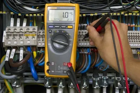
Testing before energizing is mandatory.
Common tests include:
- Insulation resistance test
- Continuity test
- Earth resistance test
- Polarity test
Skipping testing increases the risk of fire and shock.
Common Electrical Installation Mistakes
Avoid these errors:
- Undersized cables
- Improper earthing
- Overloaded circuits
- Mixing neutral and earth
- Poor joint insulation
- No labeling in DB
Small mistakes can lead to serious hazards.
Future-Proofing Electrical Installations
Modern installations should consider:
- Solar integration
- EV charging points
- Smart home systems
- Energy monitoring
- Surge protection devices
Planning for expansion prevents costly rewiring later.
Importance of Documentation
Proper documentation includes:
- Circuit schedules
- Load calculation sheets
- SLD drawings
- Testing reports
Documentation simplifies maintenance and troubleshooting.
FAQs
Earthing and protection devices are the most critical components for safety.
Possible causes include overload, short circuit, or faulty appliances.
Conduit is recommended for mechanical protection and long-term durability.
MCB protects against overcurrent, while RCCB protects against earth leakage.
Residential installations should be inspected every 3–5 years. Industrial systems require more frequent inspections.
Conclusion
Electrical installation is more than just connecting wires. It is a carefully engineered system that balances safety, efficiency, and reliability. Proper cable sizing, accurate load calculation, effective protection devices, and a low-resistance earthing system work together to prevent electrical hazards.
By following correct wiring practices, adhering to safety standards, and planning for future expansion, installations can remain safe and efficient for decades. Whether you are a student, technician, or engineer, mastering electrical installation principles builds practical confidence and professional competence.
A safe installation is not an option. It is a responsibility.