
The Maximum Power Transfer Theorem states that maximum power will transfer from source to load if and only if the load resistance is equal to the source’s internal resistance. The theorem was first presented by Moritz von Jacobi in 1840.
The maximum power transfer theorem is a tool for designing rather than circuit analysis. The theorem is purely about the transfer of power, not efficiency. In the early stages, the theorem was misunderstood as the efficiency of the circuit, notably by James Prescott Joule. According to the assumption, an electric system can’t be more than 50% efficient. But in the 1880s, Thomas Edison proved the assumption wrong and practically achieved nearly 90% efficiency of an electric circuit.

Power Transfer OR efficiency?
Efficiency is something different than power dissipation in the load. Efficiency is the ratio of power dissipated in the load and power provided by the source. The efficiency will always be increased by decreasing the source’s internal resistance.
In the Thevenin Theorem and Norton Theorem, we observed that any linear circuit can be reduced to a single source and a single resistor, except for a load resistor. In the case of a more complex circuit, the load resistor should be equal to Thevenin’s resistor after applying Thevenin’s theorem to the circuit. Thévenin’s resistor acts as the source internal resistor.
- Electrical Safety Test: 10 Quiz MCQs to Check Your Knowledge
- Basic Electrician Test – Check Your Electrical Knowledge
Maximum Power Transfer Theorem Explanation with Example
Suppose the following complex circuit is reduced to Thevenin’s resistor and Thevenin’s voltage source. Where Rth and Vth are fixed, we want to change the load resistor R such that the load gets maximum power dissipation.

Solution:
Numerical Explanation :
I want some numerical elaboration of the above example. I am going to vary the load resistor value from 1 to 8 in eight steps, and we will plot the result on a graph. Here is the value of the different values of the load resistor, the corresponding efficiency (on the left), and dissipated power (on the right).

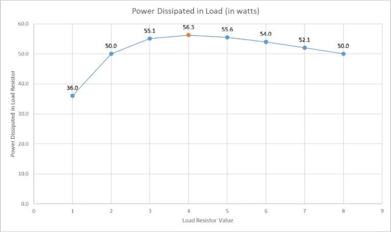
From the above data and the graph, it is easily visible that the load dissipates maximum power, i.e., 56.3 watts, when the load resistor is the same as an internal resistor (Thévenin’s resistance in this case), i.e., 4 Ohms in this case. In contrast, note another graph, given on the left, that efficiency is continuously improving as we increase the load resistor.
Maximum Power Transfer Theorem Proof :
Resistive Circuit:
Now we should proceed with the analytical proof of the above claim, as it is the local maxima of the graph if you are familiar with calculus. Suppose the following diagram, where voltage V and internal resistance of the source Ri are fixed and load resistance R is variable. We are going to find the load resistance such that maximum power is dissipated in the load. The current flowing in the circuit is:

The power dissipated in the load resistor R is PL, calculated as follows:

- 3 Methods of testing a diode with multimeter and oscilloscope
- Basic Electrician Test – Check Your Electrical Knowledge
To find the maximum power dissipation in the load, we have to minimize the denominator term in the above equation, which is a quadratic equation in variable R and contains only one global minimum. If you are familiar with calculus, to compute that minimum, we have to take the derivative of that variable and set it equal to zero.

We know that practically it is not possible to have a resistor of negative values, so the above equation becomes:

Hence, we have proved that the load resistor R should be the same as the source internal resistor Ri to have maximum power dissipation in the load.
Reactive Circuit:
Practically, every load has some non-linearity and contains some components of capacitance and/or inductance, which lead to a reactive component in the circuit. The theorem is also applicable in that case. According to the theorem, maximum power will transfer to the load if and only if the load impedance is a complex conjugate of the internal impedance of the source.
In a radio transmission system, it is the core objective to match the impedance of the radio receiver to the complex conjugate of a transmission line or antenna. So, the receiver set (which acts as a load) gets maximum power at a specific frequency.
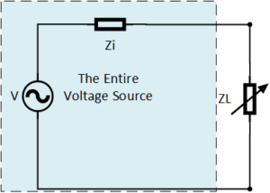
Suppose we have a fixed source voltage V, the fixed internal impedance of the source as Zi, and a variable load impedance as ZL. The current flowing through them will be I:

The power only dissipates in the resistor rather than the capacitor and inductor, so the power dissipated in the load will be:

For power to be maximum, the denominator part of the above equation should be minimum, i.e., near zero.

Plug equation (2) into equation (1), so we get the equation below:

- Home EV Charger Installation Guide: Everything You Need to Know
- Encoder in Robots: Types, Working Principle and Applications
It remains to solve the equations above for RL so that we get maximum power dissipated in the load resistor. Now the equation is the same as we started in purely resistive loads, and the solution is the same way.

Finally, load impedance ZL should be:

The above discussion has proved that the load impedance ZL should be the conjugate of the source internal Impedance Zi to have maximum power delivered to the load.
I think this talks about a lot and it’s very elaborate
This really helped thanks so much! Just a small comment, on the proof I believe the line on the derivation : (−Ri^2/R)+1=0 the R term should be squared also.
Thanks George Bick. I corrected it.