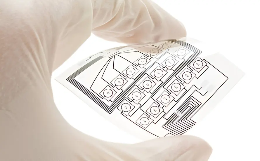
A Flexible Printed Circuit Board or Flex PCB is a type of PCB with flexible or bendable substrates on which electronic components with various functions are mounted. Some of the polymer substrates that can be used for flex PCB are polyester, polyimide, and Teflon. Flexible PCBs have gained huge traction in the field of electronics due to their usefulness as a replacement for bulky wire harnesses and cables. Its importance has flourished further, expanding its use as flexible circuits in modern electronics such as cellular phones, wearables, and laptops.
- Home EV Charger Installation Guide: Everything You Need to Know
- Encoder in Robots: Types, Working Principle and Applications
A flex PCB can have two major classifications— flex-to-install and dynamic flex. A flex-to-install needs to withstand flexing during installation. A dynamic flex, on the other hand, should be able to endure multiple bending cycles. The application of the circuit determines the best design configuration. Another major classification of Flex PCB is according to its construction and the number of conductive layers:
Single-Sided Flex Circuits
A single layer consisting of a conductive layer laminated with a flexible dielectric substrate. This is the least expensive and simplest type of flex PCB.
Double-Sided Flex Circuits
A double-sided flex circuit has two layers of conductive sheets laminated to flexible film. This construction can cost more than twice as much as single-sided flex circuits.
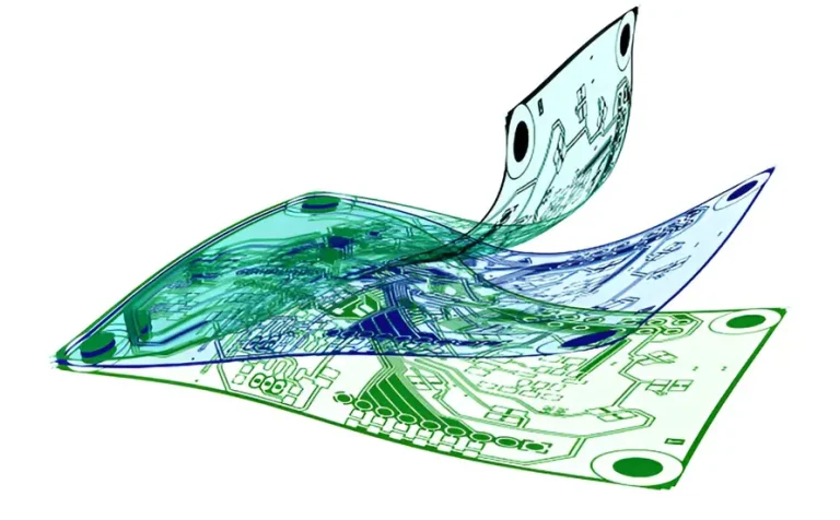
Multilayer Flex Circuits
A type of flexible board with the most complex construction is a multi-layer flex circuit. It has three or more conductive layers laminated to a flexible substrate. Vias are used to form conductive paths across the layers.
What are the Major Drivers of Flexible Circuit Boards?
Below is a summary of why many industries rely on flexible PCBs.
Flexibility.
The most significant benefit of flex PCBs is flexibility. The folds and bent areas of the PCBs can still be mounted with components, which poses a big advantage for applications with three-axis connections. This also eliminates the requirement for heavy wiring, which strengthens the reliability of the device. Both space and weight are maximized with the utilization of flexible circuit boards.
Resistance to Vibration.
Another known advantage of flexible circuit boards is their mechanical strength. The elasticity of the laminates allows the absorption of vibrational stresses. This makes flex PCBs suitable for environments with high vibrations. Flex circuits can also easily be combined with other materials to form better properties, such as water and corrosion resistance.
Package Size and Weight Reduction.
Being able to be bent and folded provides a great advantage when trying to maximize three-dimensional space in a device. The configuration of flex PCBs also allows for lighter and smaller designs. A single circuit can serve as a replacement for rigid and bulky sections of an electronic device.
What are the Common Issues in Flexible PCBs?
Despite the numerous advantages of flexible PCBs, some issues are still commonly encountered, which must be assessed, prevented, or mitigated by PCB manufacturers and assemblers.
Short Issues Due to Tight Spacings Between Solder Pads
One of the main goals of flexible circuit board design is to maximize functionality within a limited board area to achieve a small device form factor. This also means placing the solder pads of the circuit boards closer to each other, which can result in unwanted issues such as shorting. Narrow spacing between solder pads also means tighter windows during component placement and soldering processes. This issue can be addressed through design modifications by widening the distances between pads or putting tighter tolerances during PCB assembly.
Trace Crack and Delamination
Since flexible boards are widely used in dynamic applications with numerous bending and flexing cycles, poor design can potentially result in trace cracks and delamination. Flex PCBs with sharp conductor tracks and junctures serve as stress concentrators during frequent flexing. This can be prevented by making a smooth and gentle radius for conductive traces instead of sharp turns. The application of stiffeners on selected areas will also avoid bending in soldered areas. Another important design practice to combat trace cracks is to keep away from stacked traces.
Flex Base to Copper Delamination
Weak bond strength between the polymer base and copper can lead to serious delamination. A proven solution includes encapsulating unsupported pads with cover-lay insulation. An alternative solution is to make the cover-lay openings smaller than the conductive pads. Elongated pads are also preferred over sufficient pad insulation. PCB board manufacturers will have more robust fabrication processes with these design rules.
- Crane Electrical Systems: Safe, Intelligent, and Efficient Operation
- Electrical Installation Guide: Wiring, Protection & Safety Standards
Moisture Absorption
Polyimide-based laminates are most susceptible to moisture absorption, being regarded as a hygroscopic type of material. When moisture gets into the flex surfaces, delamination can potentially occur between the cover layers and the flexible area. To eliminate moisture on flexible circuit boards, a pre-baking step is done before the assembly of flex PCBs. The pre-baking step also preconditions the surface of the substrate for subsequent soldering processes. Baking temperature and time are both dependent on the thickness and type of the substrate. Thicker flex PCBs will typically require longer pre-baking times.
Component Connection Defects
Just like rigid PCBs, component connection defects can also be encountered in flexible circuit boards. For instance, lifted and misaligned components can be encountered when there is a bending of the thin substrates during component placement and reflow processes. The flex laminates should be securely fastened during processing to prevent an unstable base during the placement of electronic components and soldering.
Flex PCB Tearing
Another issue with thin substrates is the likelihood of tearing. Polyimide substrates have high initial tear strength but can suffer from catastrophic tearing once they start and propagate. A common design practice is to incorporate tear stops on all corners of the copper tracks. A minimum turn radius is also being followed on the internal corners. Flex PCB tearing should be carefully controlled by designers and PCB board manufacturers.